Selecting the correct fin tube manufacturing method is one of the most consequential decisions in an air-cooled heat exchanger specification. Extruded, high-frequency welded, and crimped fin tubes are all helical fin configurations that look similar in a drawing, but they differ fundamentally in the nature of the fin-to-tube bond. The bond determines maximum service temperature, long-term thermal performance, fouling behaviour, and ultimately the life of the heat exchanger bundle. Specifying the wrong type can result in progressive thermal performance degradation that is expensive to diagnose and impossible to reverse without re-tubing the bundle.
ZC Steel Pipe manufactures HF-welded fin tubes with carbon steel, alloy steel (A213 T11/T22/T91), and extruded bimetallic fin tubes for EPC projects in refinery, gas processing, and petrochemical facilities across Africa, the Middle East, South America, and Southeast Asia.
What we see on orders from West African gas projects: A contract for three process trim coolers specified "finned tubes per API 661" without defining the fin bond type. The equipment vendor selected tension-wound L-foot crimped aluminum fin tubes — the cheapest option that satisfies API 661 dimensional requirements. The trim coolers operate at tube-wall temperatures reaching 165 °C during compression startup. Within 8 months of commissioning, cooler outlet temperatures exceeded the process limit. Thermal survey confirmed 28% heat transfer performance loss from fin-root bond relaxation at the elevated temperature. The three bundles were replaced with HFRW welded carbon steel fin tubes at 3× the original bundle cost plus a 6-week schedule impact. Specifying the bond type on the purchase order is the only protection against this substitution — API 661 dimensional compliance does not distinguish between bond types.
Overview of the Three Manufacturing Methods
Each manufacturing method produces a different type of fin-to-tube joint. The table below summarises the key differentiators — but the numbers in the contact resistance and temperature columns are the ones that determine fit for service, not the fin geometry dimensions that appear on the fabrication drawing.
| Property | Extruded (Bimetallic) | HFRW Welded | Crimped (Tension-Wound) |
|---|---|---|---|
| Bond type | Mechanical interference | Metallurgical fusion | Mechanical tension |
| Contact resistance | Very low | Zero | Moderate to high |
| Max tube-wall temp | ~200 °C | ~450 °C (steel fin) | ~120–150 °C |
| Fin material | Aluminum (standard) | Carbon/alloy/SS steel | Aluminum or steel |
| Base tube range | Carbon, alloy, SS | Carbon, alloy, SS | Carbon, alloy, SS |
| Manufacturing speed | Moderate | High | Very high |
| Relative cost | Moderate | Moderate–high | Low |
| API 661 compliant | Yes | Yes | Yes (limited service) |
Read this table alongside the temperature limits, not as standalone numbers. The most common selection error is choosing crimped fins based on the cost and dimensional columns without accounting for the temperature limit row — particularly when process startups or steam-out cleaning conditions push temperatures above 120 °C for hours at a time.
Thermal contact resistance is a performance parameter, not a dimensional property. It does not appear on a fabrication drawing, it does not fail a dimensional inspection, and it does not affect the fin geometry in any visually detectable way. A bundle with degraded crimped fin bonds looks identical to a new bundle with HFRW bonds on every visual and dimensional check right up to the point of process performance failure. This makes fin bond degradation the most difficult heat exchanger failure mode to screen for at goods receipt — and the easiest for a supplier to introduce through material substitution. The only protection is specifying the bond type (HFRW vs extruded vs crimped) explicitly on the purchase order, then verifying it through bond test documentation (peel test or weld monitoring record) on the MTC.
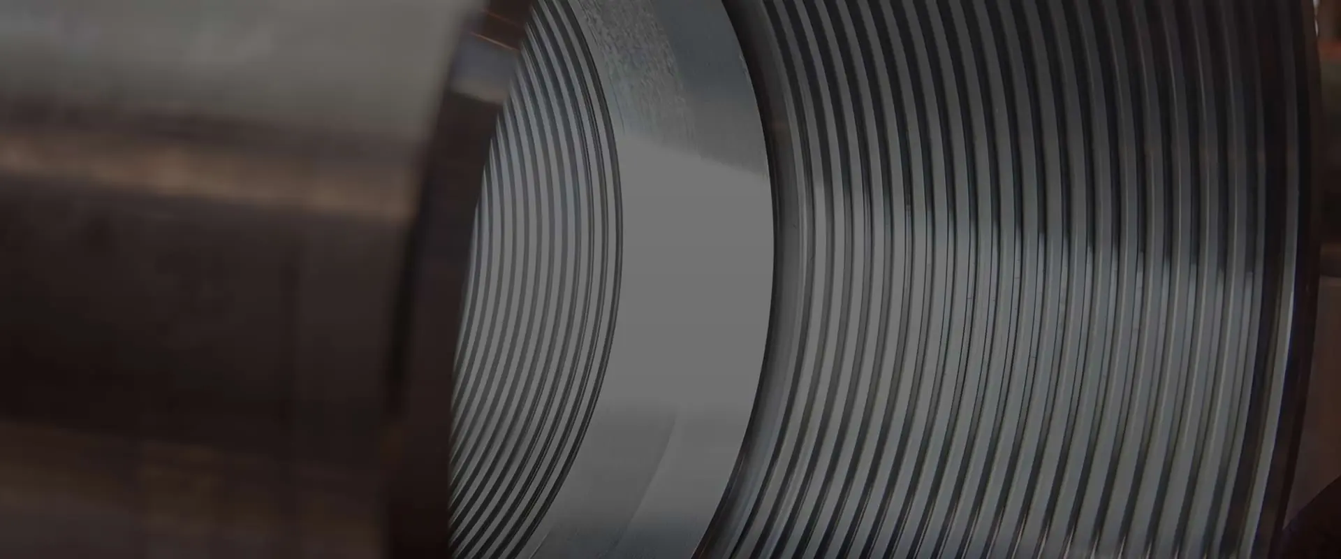
Extruded Fin Tubes
Manufacturing Process
A carbon steel or alloy steel tube is cleaned and descaled, then fed into a co-extrusion press. An aluminum billet is loaded into the press die and forced around the tube under hydraulic pressure while the tube is rotated. The die geometry forms the helical fin profile simultaneously with the extrusion. As the aluminum exits the die, it is cold-worked against the tube surface under very high contact pressure, pressing it into the micro-roughness of the tube OD. The result is a bimetallic tube with an aluminum outer shell and integral helical fins.
Fin Root Bond
The fin-root bond is mechanical, created by the cold-work interference fit between the aluminum and the steel tube. In a new extruded tube, this produces very low thermal contact resistance — typically in the range of 0.00010–0.00020 m²·K/W. This is adequate for service temperatures below 200 °C where the differential thermal expansion between aluminum and steel remains small.
Service Temperature Limit
The fundamental limitation of extruded bimetallic fins is differential thermal expansion. Aluminum expands at roughly twice the rate of steel per degree of temperature rise. At tube-wall temperatures above 200 °C, repeated thermal cycling causes the aluminum sleeve to ratchet outward relative to the steel tube, permanently opening a gap at the fin root. This gap increases contact resistance and reduces effective thermal performance, sometimes by 20–40% compared with a new tube. Once the gap forms, it cannot be closed without re-tubing.
The 200 °C limit is a normal operating limit, not a single-excursion limit. An extruded fin tube that sees 165 °C continuously but spikes to 210 °C during three startups per year is not operating within its rating — those excursions accumulate ratcheting damage with each cycle.
When to Specify Extruded Fin Tubes
Extruded bimetallic fin tubes are the standard choice for:
- Water and lube oil coolers where tube-wall temperatures remain below 150 °C
- Utility and instrument air coolers in non-refinery service
- Projects where aluminum fin material is specified for weight reduction
- Any service where tube-wall temperature does not exceed 200 °C in operation or during steam-out cleaning
For the complete dimensional requirements and peel strength testing criteria for extruded fin tubes, see the ASME Boiler Tube Spec Tables →
To convert between fin dimensions in inches and mm, use the Unit Converter →
High-Frequency Resistance Welded (HFRW) Fin Tubes
Manufacturing Process
A fin strip (typically 8–20 mm wide, 0.89–2.5 mm thick for carbon steel) is cold-formed to an L-shaped or T-shaped cross-section and fed through a guide die onto the rotating tube. As the fin strip contacts the tube surface, a high-frequency (usually 450–500 kHz) electrical current passes through the contact zone. The skin effect concentrates the current at the contact surface, generating intense local heating that melts the fin foot and tube surface metal in a zone approximately 0.2–0.5 mm deep. A pressure roll immediately behind the current contact point forges the molten metal together, expelling oxidised surface metal as a flash bead and forming a sound fusion weld.
The weld is continuous along the full length of the fin spiral. No filler metal is used. The entire bond zone is inspected by the continuity of the current flow — a gap or void breaks the current path and appears as an unmelted zone, which the operator can see immediately on the current monitor. This is the basis for the weld continuity monitoring record that should appear on the MTC for every HFRW finning run.
Fin Root Bond
HFRW produces a metallurgical fusion weld with zero thermal contact resistance at the fin root. Heat flows from the tube OD directly into the fin material without any interface resistance. This delivers the theoretical maximum fin efficiency for a given fin geometry, and performance does not degrade over time due to thermal cycling — unlike mechanical-bond fin types.
Service Temperature Capability
HFRW fin tubes with carbon steel fins can be used at tube-wall temperatures up to approximately 450 °C. With alloy steel fins (T11, T22, T91), the limit increases with the alloy composition. With stainless steel fins, HFRW fin tubes can serve at temperatures up to 600 °C or higher depending on the alloy. The base tube material, not the fin bond, becomes the limiting factor at elevated temperatures. Carbon steel base tubes to ASTM A179 are limited by oxidation and creep above 400–425 °C; A213 T11 or T22 alloy steel base tubes extend service to 510–550 °C.
Contact Resistance Impact on Overall Heat Transfer Coefficient
The following calculation shows what fin bond condition does to the overall heat transfer coefficient U for a typical forced-draft air cooler tube bundle, referred to the external fin surface area. The numbers are worked from first principles so that a specifying engineer can see exactly how much U shifts between bond types — and how much of the 28% loss described in the field case above comes from contact resistance versus physical fin detachment.
Assumed geometry and service conditions:
- Tube OD: 25.4 mm; Tube ID: 20.0 mm
- Fin pitch: 6 FPI (fins per inch)
- External surface area per metre of tube (bare tube + fins at 6 FPI): A_ext ≈ 0.789 m²/m
- Internal surface area per metre: A_int = π × 0.020 = 0.0628 m²/m
- Area ratio A_ext / A_int = 0.789 / 0.0628 = 12.6×
- Air-side heat transfer coefficient: h_o = 50 W/m²·K (typical forced-draft air cooler)
- Tube-side heat transfer coefficient (liquid service): h_i = 5,000 W/m²·K
- Fin area fraction of external surface: η_f = 0.88 (88% of A_ext is fin area)
Overall U formula (referred to external area):
U = 1 / (1/h_o + R_contact + R_wall_ext + R_internal_ext)
Where each resistance term referred to external area is:
- R_external = 1/h_o = 1/50 = 0.02000 m²·K/W (dominant resistance — air side)
- R_wall_ext ≈ 0.00005 m²·K/W (negligible for steel tube wall at this thickness)
- R_internal_ext = 1/(h_i × A_int/A_ext) = 1/(5,000/12.6) = 1/397 = 0.00252 m²·K/W
- Sum of non-contact resistances = 0.02000 + 0.00005 + 0.00252 = 0.02257 m²·K/W
Contact resistance contribution (referred to external area, scaled by fin area fraction):
| Bond condition | R_contact (fin-root) | R_contact_ext = R_contact × 0.88 | U (W/m²·K) | vs HFRW |
|---|---|---|---|---|
| HFRW welded | 0 m²·K/W | 0 | 1/0.02257 = 44.3 | baseline |
| New extruded bimetallic | 0.00015 m²·K/W | 0.00013 | 1/0.02270 = 44.1 | −0.5% |
| Degraded crimped (18 months at 140 °C) | 0.00060 m²·K/W | 0.00053 | 1/0.02310 = 43.3 | −2.3% |
Reading the table: Contact resistance alone, in isolation, accounts for a 0.5–2.3% reduction in U. This is a real but modest effect in a new or lightly degraded bundle. The 28% heat transfer loss in the field case described earlier is not explained by contact resistance alone. Physical fin detachment — where the L-foot separates from the tube surface along extended sections — eliminates that fin's contribution to heat transfer entirely, reducing the effective fin area rather than just increasing interface resistance. In severe degradation, the combined effect of increased R_contact across the surviving bonds plus zero contribution from detached fins produces the large performance losses seen in field bundles operating well above their crimped-fin temperature rating. The calculation above isolates the contact resistance mechanism to allow a specifying engineer to quantify it separately from fin detachment.
When to Specify HFRW Fin Tubes
HFRW welded fin tubes are the standard choice for:
- Refinery and petrochemical air coolers per API 661 where tube-wall temperatures exceed 150 °C
- Gas plant trim coolers and product coolers
- Fired heater convection section air preheaters and economisers
- Any application where long-term thermal performance consistency is required
- Services with frequent steam-out or hot-oil cleaning where peak temperatures may briefly exceed 200 °C
Crimped (Tension-Wound) Fin Tubes
Manufacturing Process
A fin strip with an L-shaped foot (also called LL-type) is wound onto the tube at controlled tension using a powered winding head. The L-foot bears against the tube OD. At the end of each run, the fin strip is crimped (bent down) against the tube to lock the final wrap. No heat or welding is involved. The process is very fast and requires less capital equipment than extruded or HFRW manufacturing.
Fin Root Bond
The contact between the L-foot and the tube OD is maintained solely by the tension in the fin strip. This produces a finite contact resistance that is higher than extruded or HFRW bonds and varies with manufacturing tension, tube surface condition, and service history. At moderate temperatures (below 100 °C), newly installed crimped fin tubes can have contact resistances of approximately 0.0002–0.0006 m²·K/W. As temperature rises and thermal cycling occurs, residual tension in the fin strip relaxes, increasing contact resistance further.
Service Temperature Limit
Crimped aluminum fin tubes are generally limited to approximately 120 °C, beyond which thermal stress cycling causes noticeable fin strip tension relaxation. The TEMA manual and API 661 place explicit limits on the use of tension-wound fins in elevated-temperature service. In practice, many operators accept crimped fin tubes for cooling water, lube oil, and utility air coolers, but specify HFRW for process services.
When to Specify Crimped Fin Tubes
Crimped fin tubes may be suitable for:
- Low-temperature utility coolers (cooling water, compressed air after-coolers) below 100 °C
- Budget-constrained replacement bundles in non-critical utility service
- Installations in temperate climates where maximum ambient temperature is low
Crimped fin tubes are not recommended for:
- Refinery or petrochemical process air coolers
- Any service with repeated steam-out or thermal shock
- Offshore installations where corrosion of the L-foot/tube gap accelerates fin detachment
- Long-term unattended service where performance degradation cannot be easily detected
Side-by-Side Selection Guide
| Decision Factor | Choose Extruded | Choose HFRW Welded | Choose Crimped |
|---|---|---|---|
| Tube-wall temp > 200 °C | No | Yes | No |
| Tube-wall temp 100–200 °C | Marginal | Preferred | No |
| Tube-wall temp < 100 °C | Yes | Yes | Acceptable |
| Steam-out cleaning required | No | Yes | No |
| Long-term performance guarantee | Yes (below 150 °C) | Yes | No |
| Lowest first cost | No | No | Yes |
| Offshore or humid environment | Epoxy-coated only | Preferred | No |
| Alloy steel base tube (T11/T22) | Yes (aluminum fin) | Yes (steel fin) | Limited |
| API 661 refinery service | For low-temp only | Preferred | Limited |
The critical read from this table is the "Tube-wall temp 100–200 °C" row. Extruded fins are marked marginal — not acceptable, not preferred. If the normal operating tube-wall temperature falls in that band and the service has any startup excursions, steam-out events, or is unattended for extended periods, the correct specification is HFRW. Extruded bimetallic fins in that temperature band require that the design basis accounts for every peak temperature the tube will see, not just the steady-state process temperature.
When NOT to Use Tension-Wound Crimped Fin Tubes
The following applications are incompatible with tension-wound crimped fin tubes regardless of whether the fin geometry meets the dimensional requirements of API 661.
| Application | Required alternative | Why crimped fails |
|---|---|---|
| Process air cooler, tube-wall temp > 120 °C | HFRW welded | Thermal relaxation of L-foot tension at elevated temperature increases contact resistance |
| Steam-out cleaning operations | HFRW welded | Steam temperature (150–175 °C) exceeds crimped fin bond stability; single steam-out event can cause 10–30% bond degradation |
| Refinery or petrochemical process service (API 661) | HFRW welded (preferred) | API 661 limits tension-wound fin service temperature; industry standard for process air coolers is HFRW |
| Offshore or coastal installation | HFRW with coating | Gap between L-foot and tube surface traps saltwater, creating galvanic cell that accelerates corrosion at the fin base |
| Long-term unattended operation (remote location) | HFRW welded or extruded | Performance degradation is gradual and invisible on visual inspection; cannot be detected until process excursion occurs |
| Service where long-term thermal performance guarantee is required | HFRW or extruded | Only metallurgical (HFRW) or cold-work interference (extruded at below 200 °C) bonds maintain consistent contact resistance over time |
The offshore and coastal row deserves particular attention. The L-foot sits in a narrow gap against the tube OD. In humid or saline environments, that gap wicks moisture and traps chlorides between dissimilar metals — aluminum L-foot against carbon steel tube. The resulting galvanic cell corrodes the tube surface under the fin, progressively weakening the mechanical support for the fin strip. The fins appear intact on visual inspection while the tube OD underneath is pitted and thinned. By the time the damage is visible, tube-wall integrity is already compromised.
Fin Bond Failure Modes to Specify Against
Understanding the specific mechanisms by which fin bonds fail makes it possible to write procurement language that closes each failure path. The three modes below cover the failures we see most frequently in bundles that enter service with the wrong fin type or with undetected substitution.
Failure Mode 1 — Crimped fin bond relaxation from thermal cycling
Mechanism: Tension-wound L-foot aluminum fin tubes installed in a process air cooler with a design tube-wall temperature of 95 °C — within the crimped fin 120 °C limit on paper. However, during plant startup, the cooler bypasses its rated flow for 6–8 hours, causing tube-wall temperature to reach 145 °C on three occasions in the first operating year. Each thermal cycle above 120 °C relaxes the L-foot tension further. After three excursions, the contact pressure at the fin root drops below the threshold for reliable thermal contact. Contact resistance increases by 0.0005 m²·K/W per fin, compounding across the full tube length.
Diagnostic: Process outlet temperature rises progressively over 12–18 months against flat process inlet conditions. Infrared thermography shows uneven surface temperature distribution on the tube faces — hot bands where fin contact has degraded alternate with cooler bands where contact remains. Physical fin pull-off test on a removed sample tube confirms reduced force-to-detach versus a new reference tube. The API 661 bond strength acceptance criterion is no longer met.
Fix: Replace the bundle with HFRW welded fin tubes rated to the maximum process excursion temperature, not just the normal operating temperature. Add an operating procedure specifying maximum allowable bypass duration and tube-wall temperature during startup — and make it a hold point in the commissioning checklist, not a note in the operating manual.
Failure Mode 2 — Steam-out cleaning destroying extruded bimetallic fin bond
Mechanism: Extruded bimetallic aluminum fin tubes in a lube oil cooler operating at 90 °C tube-wall temperature are cleaned with live steam during a planned turnaround. Steam temperature at the cooler inlet is 165 °C — 35 °C above the extruded fin temperature limit. During the 4-hour steam-out, differential thermal expansion between aluminum and steel permanently opens a gap at the fin root along the entire length of several tube passes. The cooler returns to service with intact-appearing fins but 18% thermal performance loss.
Diagnostic: Post-turnaround performance test shows reduced duty versus pre-turnaround baseline with no change in process conditions. Thermographic scan confirms hot tube bands in the same row positions that received steam-out flow. Fin mechanical integrity appears normal — the fins do not fall off — so the failure is entirely thermal-performance, not structural. This is the most commonly missed diagnosis in post-turnaround heat exchanger performance investigations.
Fix: Include the steam-out temperature in the design basis for fin tube selection from the first specification document, not as an afterthought in the inspection and testing plan. For any service where steam-out cleaning at temperatures above 150 °C will be used, specify HFRW welded fin tubes regardless of the normal operating tube-wall temperature. The normal operating temperature and the cleaning temperature must both appear in the equipment specification.
Failure Mode 3 — Supplier drawing approval for wrong fin type
Mechanism: The datasheet requires "HFRW welded fin tubes, API 661." The vendor submits a dimensional drawing showing the correct fin pitch, height, and OD. The drawing review approves the geometry without verifying the manufacturing method. The word "HFRW" does not appear on the vendor drawing; the fin root cross-section is not detailed enough to distinguish a weld profile from a crimped L-foot. The vendor manufactures tension-wound crimped fins and delivers equipment that passes incoming dimensional inspection at the fabrication yard.
Diagnostic: The only way to confirm the manufacturing method at goods receipt is to check two things that are not present on a dimensional drawing: (1) review the MTC for weld monitoring records (HFRW) or peel test records (extruded) — absent records confirm crimped fins regardless of what the PO stated; (2) examine the fin root cross-section under magnification — an HFRW weld shows a visible fusion zone with expelled flash bead; a crimped L-foot shows a flat contact surface with no weld evidence.
Fix: Add to the MTC requirements as a hold point, not a review point: "HFRW fin tubes to include current-continuity weld monitoring chart for each finning run. Extruded bimetallic fin tubes to include peel strength test report per API 661 Section 4. Absence of either document is grounds for rejection of the entire delivery." This language closes the substitution path completely — a supplier cannot deliver crimped fins against an HFRW order without also falsifying MTC documentation.
Purchase Order Guidance
A purchase order for fin tubes must explicitly state the fin bonding method. Do not rely on the word "helical fin tube" alone — state one of: extruded bimetallic, HFRW welded, G-type embedded, or tension-wound. The bonding method directly determines the applicable temperature limit and testing requirements under API 661.
Procurement trap — fin bond type left unspecified, allowing crimped fin substitution:
Wrong PO: "Helical fin tubes, 6 FPI, 12.7 mm fin height, 25.4 mm OD base tube, API 661."
What ships: The supplier selects tension-wound crimped L-foot aluminum fins — identical dimensions, fully API 661 compliant on paper. No bond test is required by API 661 for crimped fins (peel test is only required for bimetallic extruded). The vendor's dimensional drawing shows the correct fin geometry; the bond type does not appear on the drawing. The equipment passes incoming dimensional inspection, is installed, and the performance shortfall does not become visible until months into operation when tube-wall temperature has had time to relax the fin strip tension.
Correct PO: State the fin bond method explicitly — one of: "HFRW high-frequency resistance welded" or "extruded bimetallic." Add: "Weld continuity monitoring records for each finning run (for HFRW) to be included on MTC" or "Peel strength test per API 661 Section 4 (for extruded bimetallic) to be included on MTC." Add: "Maximum tube-wall design temperature confirmed against fin type and fin material temperature limit — stated as [°C] in the equipment specification."
Procurement trap — steam-out temperature not included in the design basis: Many operators specify tube-wall temperature based on normal operating conditions but overlook the peak temperature during steam-out cleaning (typically 150–175 °C). An extruded fin tube rated for a 120 °C operating condition will experience fin-root bond degradation if steam-out cleaning is applied, especially if steam-out is repeated annually. Always check that the fin tube type can withstand the maximum temperature of all operating and cleaning conditions, not just the normal operating temperature.
Procurement trap — accepting crimped fins as equivalent to extruded: In some markets, suppliers substitute tension-wound crimped fin tubes when the specification says "low-fin" or "helical fin" without further qualification. Always review supplier's dimensional drawings and process capability documentation to confirm that the supplied fin type matches the specified bonding method before approving the drawing package.
Frequently Asked Questions
What is an extruded fin tube?
An extruded fin tube is a bimetallic tube in which an aluminum outer sleeve is hot-extruded over a steel, alloy steel, or stainless steel inner tube using a die that simultaneously forms the helical fins. The extrusion process forces aluminum into the micro-surface irregularities on the inner tube, creating mechanical interference contact with very low thermal contact resistance at the fin root. Extruded fin tubes are the standard choice for air-cooled heat exchangers in moderate-temperature service up to approximately 200 °C (400 °F).
What is a high-frequency welded fin tube?
A high-frequency welded (HFRW) fin tube is made by spirally winding a continuous fin strip onto a rotating tube and simultaneously welding the fin foot to the tube OD using high-frequency resistance current. The current is concentrated at the fin foot-to-tube contact zone, where it melts both surfaces just before a pressure roll forges them together, creating a continuous metallurgical fusion weld. The result is zero contact resistance at the fin root and the ability to operate at tube-wall temperatures up to 450 °C for carbon steel fins or higher for alloy steel fins.
What is a crimped or tension-wound fin tube?
A crimped fin tube (also called a tension-wound or LL-type fin tube) is made by winding a fin strip with an L-shaped foot under high tension so that the foot bears tightly against the tube surface. The contact pressure is maintained by the residual tension in the fin strip alone — there is no chemical or metallurgical bonding. Crimped fins offer the simplest manufacturing process and the lowest cost but also have the highest thermal contact resistance of the three types. They are suitable for moderate service temperatures below approximately 120–150 °C where thermal relaxation of the fin strip tension does not degrade the contact bond.
How does fin bond type affect heat transfer performance?
The fin bond determines the thermal contact resistance (Rc) at the fin-root-to-tube junction. A metallurgically bonded HFRW fin has near-zero contact resistance (Rc ≈ 0 m²·K/W). An extruded bimetallic fin has a very low Rc due to the cold-work interference fit. A tension-wound crimped fin has a finite and variable Rc that increases with time and temperature as the fin strip tension relaxes. Higher Rc means less heat flows through the fin root, reducing the effective fin efficiency and the overall heat transfer coefficient of the bundle — sometimes by 15–30% in a degraded crimped fin tube compared with a new one.
At what temperature do extruded aluminum fin tubes lose their bond?
Extruded aluminum fin tubes are generally limited to a maximum tube-wall temperature of approximately 200 °C (400 °F). Above this temperature, the difference in thermal expansion coefficients between aluminum (23 × 10⁻⁶ /°C) and steel (12 × 10⁻⁶ /°C) causes the aluminum sleeve to expand away from the steel tube and open the fin-root contact. This increases thermal contact resistance and progressively degrades heat transfer performance. API 661 specifies a maximum tube metal temperature for extruded bimetallic fin tubes to limit this effect.
Which fin tube type should I specify for a refinery air cooler?
For refinery air-cooled heat exchangers in hydrocarbon service with tube-wall temperatures above 100 °C, specify high-frequency welded fin tubes with carbon steel or alloy steel fins per API 661. HFRW tubes eliminate the risk of fin bond degradation at elevated temperatures and are the standard for API 661 refinery service. Extruded bimetallic aluminum fin tubes are suitable for utility air coolers with tube-wall temperatures below 200 °C, such as water or lube oil coolers. Avoid tension-wound crimped fins for any service above 120 °C or where long-term thermal performance consistency is critical.
What standards govern finned tube procurement for refinery service?
API Standard 661, Air-Cooled Heat Exchangers for General Refinery Service, is the primary standard governing fin tube type, dimensions, testing, and material requirements for refinery and petrochemical air coolers. API 661 defines minimum fin thickness, fin bond peel strength for bimetallic tubes, and maximum design temperatures for each fin type. Project specifications typically reference the latest edition of API 661 and add project-specific requirements for fin materials, tube materials, and inspection. For shell-and-tube heat exchangers with low-fin tubes, TEMA (Tubular Exchanger Manufacturers Association) Standards apply.
How do I verify the fin bond type at goods receipt?
Dimensional inspection cannot distinguish between HFRW welded, extruded bimetallic, and tension-wound crimped fin tubes — all three can be manufactured to identical fin geometry. To verify the bond type at goods receipt, review the MTC for weld continuity monitoring records (HFRW) or peel strength test records (extruded bimetallic per API 661 Section 4). For HFRW tubes, the weld monitoring chart shows continuous current during each finning run. Absence of either document strongly suggests crimped fins, regardless of what the purchase order stated. A physical cross-section of the fin root under magnification shows a visible fusion zone with expelled flash bead for HFRW and a flat contact surface for crimped.
What is the difference between an L-foot and a G-type embedded fin?
An L-foot (LL-type) fin strip has a right-angle foot that bears against the tube OD under tension — this is the crimped fin. A G-type or embedded fin is made by cutting a helical groove in the tube OD and pressing the fin strip root into the groove so that tube metal is deformed over both sides of the fin foot, locking it mechanically. Embedded fins offer better bond stability than tension-wound L-foot fins but cannot match the zero-resistance metallurgical bond of HFRW welded fins. G-type embedded fins are rated to approximately 150–200 °C depending on material combination.