Scale and fouling are the most common causes of heat exchanger underperformance, and the most frequently underestimated during initial design. A bundle sized to TEMA fouling factors at the design stage will still fall short of duty if fouling rates in service exceed the design assumptions — which they often do in cooling water circuits with variable water chemistry, in seawater coolers with inconsistent biocide dosing, or in process heat exchangers handling crude fractions above 60°C. Understanding which scale types form in a given service, which cleaning method removes them without damaging the tubes, and how to interpret performance data as a cleaning trigger is what separates scheduled maintenance from unplanned shutdowns.
ZC Steel Pipe supplies seamless heat exchanger and boiler tubes to SA-179 and SA-213 T11/T22/T91, and we encounter tube cleaning questions regularly when customers return for replacement bundles — usually because tube damage during incorrect cleaning has shortened the expected tube life.
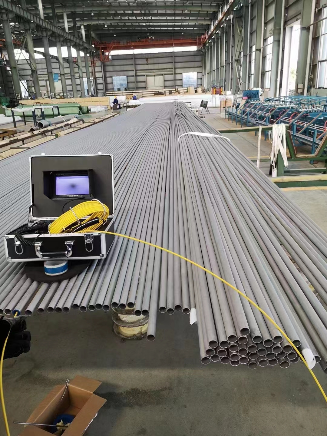 Seamless stainless heat-exchanger tubes staged alongside a borescope inspection kit.
Why Heat Exchanger Tubes Scale and Foul
Fouling deposits form when something that was dissolved in a fluid comes out of solution and adheres to the tube surface. The driver is almost always a change in temperature, velocity, or concentration at the tube wall relative to the bulk fluid.
Calcium carbonate (CaCO₃) scale is the most common deposit in cooling water systems. It forms when water temperature rises above approximately 50–60°C, reducing CO₂ solubility and shifting the carbonate equilibrium toward precipitation. Cooling tower return water — typically 40–45°C — sits close to this threshold, and scale deposits wherever the tube wall temperature locally exceeds it. CaCO₃ scale is white, moderately hard, and dissolves readily in dilute HCl. It is the easiest common scale to treat chemically.
Calcium sulfate (CaSO₄) scale has inverse solubility — it deposits more aggressively as temperature rises. It appears on high-temperature tube surfaces in cooling water circuits and in evaporator services. CaSO₄ is significantly harder than CaCO₃ and does not dissolve in HCl; it requires EDTA chelation or mechanical removal.
Silica scale (SiO₂ and magnesium silicate) forms in cooling water with high silica content (typically >150 mg/L at pH < 7). It is the hardest common deposit and resists both acid and mechanical cleaning. Silica-dominated systems require water treatment (pH adjustment, anti-silica inhibitors) at the source rather than relying on tube cleaning to manage the problem.
Biological fouling (biofilm) forms in cooling water and seawater systems at moderate temperatures (15–45°C). A biofilm of 0.1–0.5 mm thickness can reduce heat transfer coefficients by 10–15% and create the under-deposit anaerobic conditions that accelerate microbiologically influenced corrosion (MIC) on carbon steel and 304 stainless. Biofilm is removed by biocide treatment (chlorine, chlorine dioxide, quaternary ammonium) or mechanical cleaning, but recolonises within weeks without ongoing chemical management.
Corrosion deposits (magnetite, FeO·Fe₂O₃) accumulate in boiler circuits and closed cooling water loops from corrosion of carbon steel components upstream. These iron oxide deposits are non-scaling in the traditional sense but are highly insulating — magnetite has a thermal conductivity approximately 20 times lower than carbon steel — and their accumulation on boiler tube inner surfaces is one of the primary causes of tube overheating and eventual failure.
Fouling Factors in TEMA Design
The TEMA fouling factor (fouling resistance, Rf, in m²·K/W) is added to the thermal design calculation to ensure the exchanger is sized with enough surface area to deliver required duty at end-of-run fouled condition. Standard values from TEMA (Table RGP-T-2.4) include:
| Fluid type | Typical Rf (m²·K/W) |
|---|---|
| Cooling tower water (treated) | 0.0002 |
| River water (above 52°C) | 0.0004 |
| Seawater (carbon steel tubes) | 0.0002 |
| Seawater (CuNi or Ti tubes) | 0.0001 |
| Treated boiler feedwater (above 52°C) | 0.0002 |
| Boiler feedwater (below 52°C, deaerated) | 0.0001 |
| Crude oil (above 65°C) | 0.00051 |
| Light hydrocarbons | 0.0002 |
These values are not universal — they represent typical fouling rates in well-operated facilities. Actual fouling rates in specific facilities can be higher or lower depending on water chemistry, flow velocity, and treatment. They are design inputs, not performance guarantees.
The TEMA fouling factor effectively adds thermal resistance equivalent to a thin insulating layer on the tube surface. For a process-to-cooling-water HX with clean U = 800 W/m²·K, adding Rf = 0.0002 m²·K/W on each side gives a fouled overall coefficient of: U_fouled = 1 / (1/800 + 0.0002 + 0.0002) = 1 / (0.00125 + 0.00040) = 606 W/m²·K — a 24% reduction. To compensate and still hit the required heat duty at fouled condition, the exchanger is designed with 24% excess surface area over the clean-duty requirement. This is the cost of fouling, built into the capital cost at the design stage.
Recognising When Cleaning Is Needed
Performance degradation from fouling shows up in operating data before it becomes visible to inspection. Three quantitative indicators:
Hot-side outlet temperature drift: If the process fluid inlet conditions (flow rate, inlet temperature) are stable but the hot-side outlet temperature is rising above its design value, heat is not being rejected efficiently. The cold-side outlet temperature will also be lower than design. Plotting outlet temperature trend over time shows when cleaning should be scheduled.
Tube-side pressure drop increase: Scale deposits on the tube inner surface increase roughness and reduce the effective flow area. A 10–15% increase in tube-side pressure drop at constant flow is a common threshold for unscheduled inspection.
U-value calculation from operating data: The overall heat transfer coefficient can be back-calculated from operating temperatures and flow rates. When U_operating falls below approximately 75–80% of the design U_clean value, cleaning is typically economically justified on most fouling services.
A practical cleaning trigger for cooling water services is a combination of: scheduled interval (typically every 12–18 months in hard-water service, every 24–36 months for softened or deionised water), plus an unscheduled trigger if outlet temperature deviates by more than 5°C from design at steady-state conditions.
What we see in replacement tube enquiries: When customers return for replacement tube bundles after a premature failure, the most common explanation is not corrosion or material failure — it is scale-induced overheating. In fire-tube boilers and waste heat boilers in particular, calcium carbonate scale on the waterside tube surface acts as insulation, preventing heat from conducting away from the hot tube wall. The tube wall temperature rises above the allowable range for carbon steel — SA-179 loses tensile strength rapidly above 370°C — and bulging or rupture follows. Cleaning intervals in these units need to be based on water hardness and scale growth rate, not on calendar time.
Cleaning Methods for Tube-Side (Shell-and-Tube Heat Exchangers)
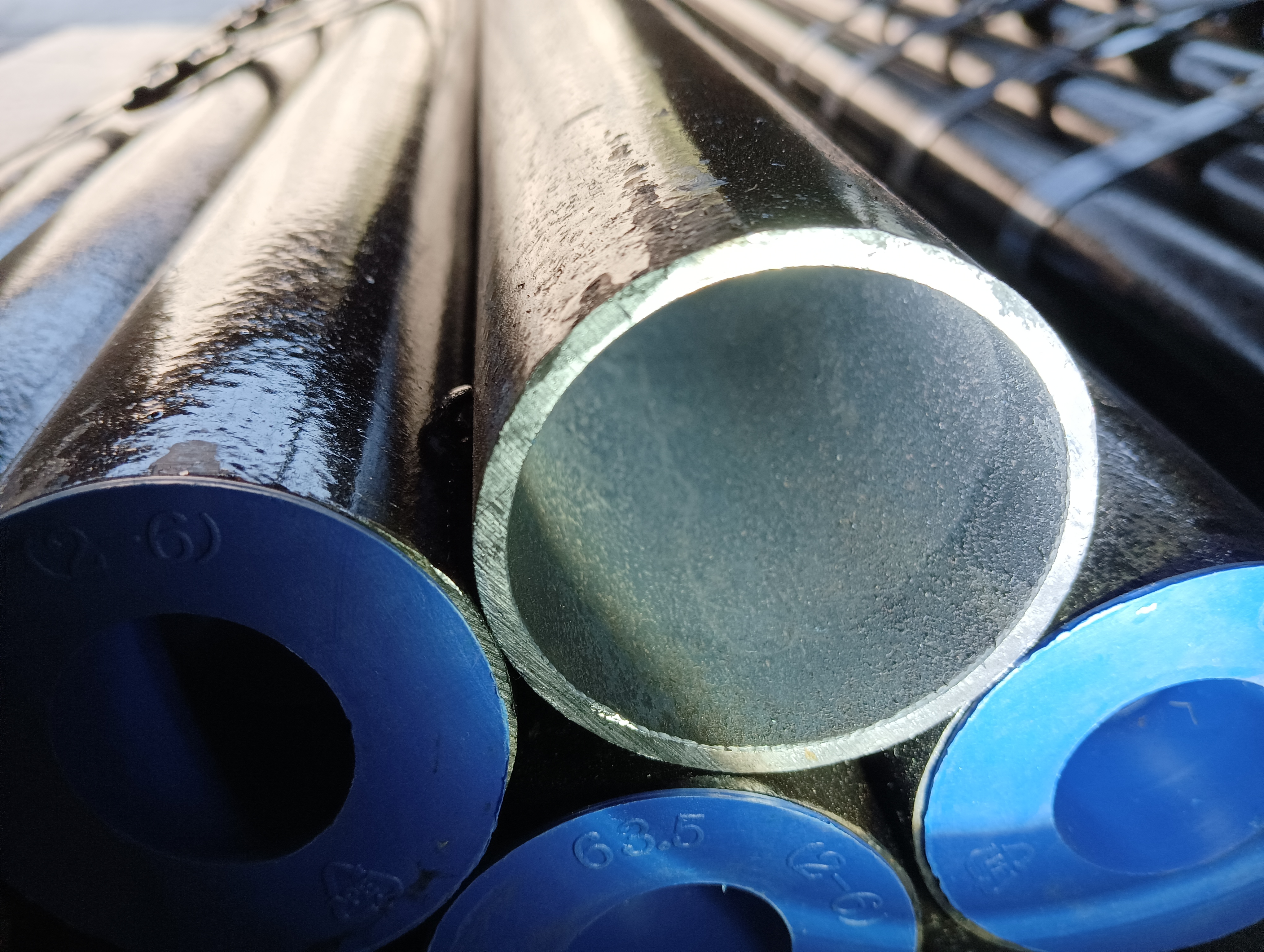 Close-up of a seamless heat-exchanger tube end with a clean, bright bore.
Mechanical Cleaning
Tube brushes inserted into straight tube passes are the simplest cleaning method: effective against soft scale (carbonate, biofilm, loose corrosion product), inexpensive, and compatible with all tube materials. Limitations: cannot navigate bends (U-tubes are not accessible at the U-bend return), cannot remove hard scale (CaSO₄, silica), and can damage thin-wall tubes or ERW seam welds if metal-bristle brushes are used on weld-sensitive materials.
For heavier deposits, rotary lancing — a rotating high-pressure water nozzle on a flexible lance — combines mechanical action with hydraulic energy. Effective against moderate carbonate scale and biofilm in straight tubes up to 3–4 m per pass before the lance stiffness limits reach.
Hydroblasting
High-pressure water jetting at 200–700 bar is the standard industrial method for tube-side descaling. At 350–500 bar, a focused lance jet will remove calcium carbonate scale and biofilm from a typical carbon steel tube at rates of 5–10 m/min lance travel. At 600–700 bar, moderate calcium sulfate scale can be partially removed, though hard silica scale typically requires chemical pre-softening before hydroblasting is effective.
Equipment requirements: Hydroblasting above 200 bar requires a certified pump unit, trained operators, and PPE rated for the working pressure. The pressure chosen for a given application must be below the yield threshold of the tube material at that OD and wall thickness — at 700 bar, thin-wall tubes (below approximately 2 mm wall in standard carbon steel) can dent or buckle at the tube-to-tube-sheet joint.
Chemical Cleaning (In-Situ Circulation)
Chemical cleaning circulates a cleaning solution through the tube bundle without disassembly. Procedure:
- Isolate and drain the heat exchanger
- Connect temporary injection and return connections at the tube-side inlet and outlet
- Circulate cleaning solution at low velocity (0.5–1.0 m/s) for 2–8 hours depending on scale thickness and chemistry
- Flush with clean water until pH and iron content of the flush water reach acceptable levels
- Passivate carbon steel surfaces (sodium nitrite or similar inhibitor) to prevent flash corrosion
Cleaning chemicals by scale type:
| Scale type | Cleaning agent | Notes |
|---|---|---|
| CaCO₃ (carbonate) | 5–10% inhibited HCl | Do not use on CuNi or brass |
| Fe₃O₄ (magnetite) | EDTA chelating agent (ammoniated) | Preferred for boiler circuits |
| CaSO₄ (sulfate) | EDTA + mechanical pre-treat | Hard scale; limited chemical removal |
| Silica (SiO₂) | HF (hydrofluoric acid) | Specialist operation only — extremely hazardous |
| Biofilm | Oxidising biocide (NaOCl) + detergent | Remove biofilm before acid cleaning |
| Fatty acids / organic | Caustic soda (2–5% NaOH) + surfactant | Saponification removes organic deposits |
Inhibited HCl must not be used to clean copper-nickel tubes (90/10 or 70/30 CuNi), admiralty brass, or any copper-alloy bundle. HCl dissolves copper alloys rapidly even at low concentrations. Use ammoniated EDTA or citric acid solutions for copper-alloy tube cleaning. Verify the tube material on the MTR before selecting a cleaning agent — copper-nickel and carbon steel tubes can look identical after years of service, and the consequences of using HCl on CuNi are severe.
Cleaning Methods for Air-Cooled Heat Exchangers (Finned Tubes)
Air-cooled heat exchanger bundles foul on the air side — the external fin surface — with dust, pollen, insects, and in coastal or industrial environments, hydrocarbon mist, salt crystallites, or process vapour condensate. Fouling on the fin surface increases air-side resistance, reduces the air-side heat transfer coefficient, and in severe cases partially blocks airflow through the bundle.
Compressed air lancing removes loose dust and fibrous debris between fins. Effective for routine maintenance in clean environments (indoor bundles, dry-climate plants). Not effective against compacted scale, oil films, or wet deposits.
Low-pressure water washing (50–100 bar) is the standard method for moderate fouling. Nozzle is directed perpendicular to the fin bank from the air-inlet face (the face the air enters), jetting in the same direction as normal airflow. Wash from inlet face to outlet face — never from the outlet face into the bundle.
Chemical foam cleaning applies a biodegradable detergent foam to the fin surface using a spray lance, allowing it to dwell for 10–20 minutes before rinsing. Effective for oily or sticky deposits where water alone does not penetrate the fin-to-fin gaps. The foam expands to fill inter-fin spaces, carrying detergent into contact with the fouled surfaces without high-velocity jetting.
The fin-bending problem: The most common maintenance mistake we see damage air-cooled bundles is fin cleaning from the wrong face or at excessive pressure. Cleaning from the air-outlet face drives debris deeper into the bundle and bends fins in the upstream direction, creating permanent bypass channels that high-velocity air flows through preferentially rather than through the clean fin passages. A bundle with 15–20% of fin tips bent inward can lose 10–15% of its thermal performance permanently — the bent fins cannot be straightened in situ. Cleaning from the air-inlet face at 60–80 bar is sufficient for most fouling conditions and avoids damage.
Post-Cleaning Inspection and Tube Acceptance
Chemical cleaning should always be followed by inspection before returning the exchanger to service. For tube-side cleaning:
- Visual inspection of tube ends for residual scale, pitting, or mechanical damage from the cleaning lance
- Eddy current testing for tube wall loss and pitting — particularly important after acid cleaning, which can accelerate corrosion if inhibitor concentration was inadequate or temperature exceeded the inhibitor's effective range
- Hydrostatic pressure test at 1.5× design pressure after chemical cleaning on critical services, to confirm no tube cracking occurred during cleaning (acid embrittlement of high-strength tubes is a non-zero risk)
For finned tube bundles after water jetting:
- Visual check of fin tip condition — count bent fins per row as a percentage of total
- Air-side pressure drop measurement at a fixed fan speed to confirm flow has been restored to pre-fouling levels
- Thermal performance test if process conditions allow — confirm outlet temperatures have returned to design values
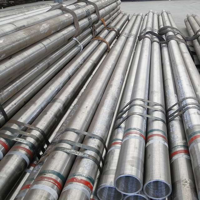 Stacked seamless tube bundles with painted ID bands for grade traceability.
Maintenance Scheduling Recommendations
| Service type | Recommended cleaning interval |
|---|---|
| Cooling tower water, moderate hardness (100–200 mg/L CaCO₃) | Every 12–18 months |
| Cooling tower water, soft water (<100 mg/L) with chemistry treatment | Every 24–36 months |
| Seawater (carbon steel tubes, no biocide) | Every 6–12 months (biofouling dominated) |
| Seawater (CuNi tubes, biocide maintained) | Every 24–36 months |
| Fire-tube boiler, hard water (>200 mg/L hardness) | Every 6 months or per water analysis |
| Water-tube boiler, treated feedwater | Annual inspection, cleaning as needed per eddy current |
| Air-cooled HX, coastal/industrial environment | Every 3–6 months (low-pressure water wash) |
| Air-cooled HX, clean inland environment | Annually or as needed per performance data |
These intervals are starting points — actual schedules should be adjusted based on operating data. A plant that tracks U-value trend over time can extend cleaning intervals when fouling rates are lower than expected and shorten them when water chemistry degrades. Fixed-calendar-interval cleaning without performance monitoring wastes maintenance resources on some bundles while missing the ones that are actually fouling fast.
For tube material specifications and wall thickness, see the ASME B36.10M specification tables → and use the unit converter → for dimensional conversions.
Frequently Asked Questions
What causes heat exchanger tubes to scale?
Heat exchanger tube scaling occurs when dissolved mineral salts in the cooling or process water precipitate out of solution and deposit on the tube surface. The most common scale in cooling water circuits is calcium carbonate (CaCO₃), which precipitates when water temperature rises above approximately 60°C or when CO₂ is outgassed at the tube surface. Calcium sulfate (CaSO₄) deposits at higher temperatures and is harder than carbonate scale. Silica scale forms in water with high silica content and is extremely hard — almost impossible to remove by acid cleaning alone. Biological fouling (biofilm from bacteria, algae) is a separate fouling mechanism that is removed by biocide treatment or mechanical cleaning.
How does fouling affect heat exchanger performance?
Fouling increases the thermal resistance between the two fluids, reducing the overall heat transfer coefficient (U-value) and lowering heat duty at constant flow rates. A typical cooling water fouling resistance of 0.0002 m²·K/W on both sides of a clean heat exchanger with U = 800 W/m²·K reduces U to approximately 606 W/m²·K — a 24% reduction. The effect compounds over time: as U drops, the heat exchanger must work harder (the hot-side outlet temperature rises or the cold-side outlet temperature falls) to deliver the same duty, which can cascade into process performance problems and plant derating.
What is the TEMA fouling factor, and how is it used in design?
The TEMA fouling factor (also called fouling resistance, Rf) is a thermal resistance value in m²·K/W added to the heat exchanger design calculation to account for the expected steady-state fouling layer on the tube surface. TEMA specifies fouling factors for different fluid types: cooling tower water is typically 0.0002 m²·K/W, seawater 0.0001–0.0002 m²·K/W, treated boiler feedwater 0.0001 m²·K/W, and crude oil above 65°C approximately 0.00051 m²·K/W. These values are used at the design stage to size the heat exchanger with adequate excess surface area, so the exchanger can still meet duty at end-of-run fouled condition without a shutdown.
What is hydroblasting and when is it used for heat exchanger tube cleaning?
Hydroblasting is high-pressure water jetting used to remove scale, biofilm, and corrosion deposits from heat exchanger tubes. Tube-side hydroblasting uses lances inserted into straight tubes at pressures typically between 200 and 700 bar, depending on scale hardness. It is effective against carbonate scale, biological fouling, and soft deposit layers. Hydroblasting cannot navigate U-tube bends or remove hard silica scale efficiently — those applications require chemical cleaning. Shell-side and fin-tube air-cooled bundles are hydroblasted from the face of the fin bank at 50–150 bar, with the nozzle oriented perpendicular to the fins to avoid bending fin tips.
What chemicals are used for descaling heat exchanger tubes?
Inhibited hydrochloric acid (5–10% HCl with a corrosion inhibitor) is the standard chemical for removing calcium carbonate scale from carbon steel and alloy steel tubes. The inhibitor is critical — uninhibited HCl attacks the tube base metal at significant rates. EDTA chelating agents are used for iron oxide (magnetite) deposits in boiler circuits without the risk of base-metal attack. Caustic soda (NaOH, 2–5%) removes fatty acid deposits and some oil films. Ammoniated solutions are used for copper alloy tube descaling — HCl cannot be used on copper or copper-nickel tubes. Phosphoric acid (low concentration) is used for mild carbonate removal in stainless steel systems where chloride stress corrosion cracking risk rules out HCl.
How do you clean finned tube air-cooled heat exchangers?
Air-cooled heat exchanger fin bundles are cleaned by compressed air lancing (for loose dust), low-pressure water washing (50–100 bar) from the air-inlet face perpendicular to the fins, or chemical foam application for oily deposits. The critical technique is jetting direction: always jet from the air-inlet face toward the outlet, never in reverse. Reverse jetting drives dirt deeper into the fin bank and risks bending fins in the direction of flow, creating bypass channels that permanently reduce air-side flow and heat transfer. Bent fins are a common result of incorrect fin cleaning by maintenance crews unfamiliar with the equipment.
How can you tell when a heat exchanger needs cleaning?
The primary indicator is a drop in thermal performance: the hot-side outlet temperature rises above its design value at constant flow, or the cold-side outlet temperature falls. Secondary indicators are increased pressure drop across the tube side (indicating partial tube blockage or heavy scale) and visible discoloration or scale deposits during inspection. A quantitative method is to calculate the fouled U-value from operating data and compare it with the clean design U-value — when the ratio falls below approximately 0.75–0.80, cleaning is usually economically justified. Many refineries and power plants schedule tube cleaning on a fixed interval (typically 12–36 months depending on water quality) rather than waiting for performance degradation.
What cleaning methods damage heat exchanger tubes?
Several cleaning methods can damage tubes if applied incorrectly. High-concentration HCl without inhibitor attacks carbon steel and removes base metal. Cleaning with ammonia-based solutions on copper-nickel or brass tubes causes stress corrosion cracking. Mechanical drilling or steel-brush cleaning of ERW (welded) tubes can open the seam weld if the brush engages the weld bead. Hydroblasting at excessive pressure on thin-wall tubes (less than 2 mm wall) can cause denting or buckling, particularly at tube-to-tube sheet joints. Post-cleaning inspection — eddy current testing for wall loss and pitting — is recommended after any chemical cleaning to confirm tube integrity before returning the exchanger to service.