Under API Specification 5CT, 11th Edition (December 2023, with Errata 1 of May 2024), Grade P110 is defined almost entirely by a mechanical envelope: minimum yield 758 MPa (110 ksi), maximum yield 965 MPa (140 ksi), minimum tensile 862 MPa (125 ksi), quenched and tempered, with no hardness limit and no chemistry beyond 0.030 % phosphorus and 0.030 % sulfur (Tables C.3, C.4 and C.5). Nearly every other requirement buyers assume is automatic on P110 is either a purchase-agreement lever or does not exist. This page says which cells are blank and which clause fills each one.
ZC Steel Pipe supplies API 5CT casing from 4½″ to 20″ and tubing from 1.050″ to 4½″ across the grade range, seamless and electric-welded, into West and North Africa, the Middle East, South America and Southeast Asia.
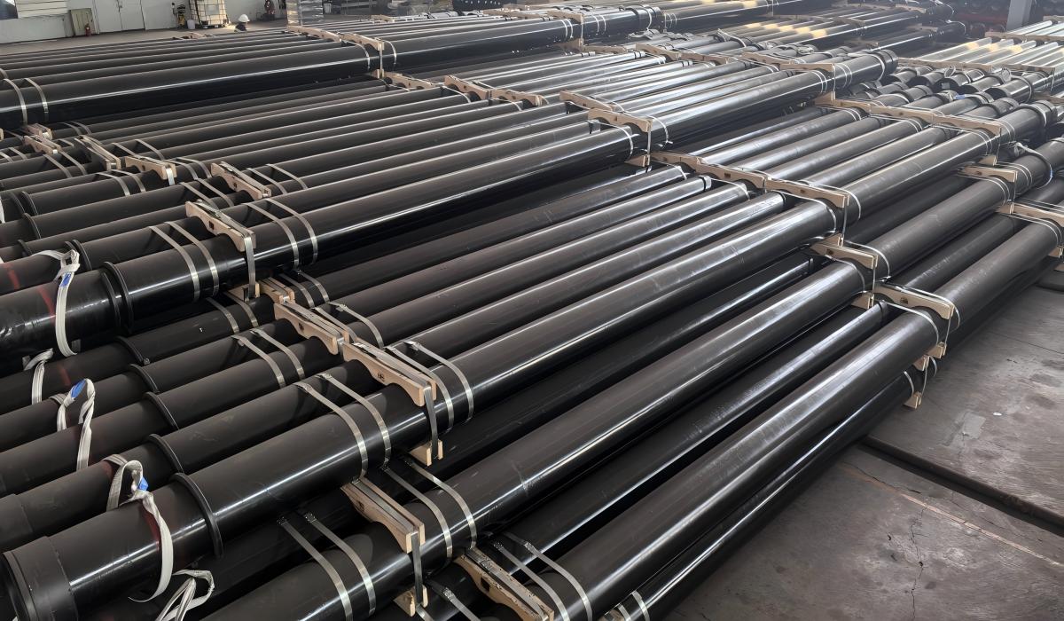
High-strength premium casing racked on timber dunnage before strapping. Nothing visible at this stage distinguishes a 760 MPa heat from a 950 MPa one — both conform.
What API 5CT actually fixes about P110
Three tables carry the whole grade definition, and the useful reading is by empty cell.
| Table C.3 / C.4 / C.5 cell | P110 value | What fills the gap |
|---|---|---|
| Manufacturing process (C.3 col 3) | S or EW, footnotes g and h | 5.1 — EW only when A.6 (SR 11) is on the purchase agreement |
| Heat treatment (C.3 col 4) | Q — quenched and tempered | mandatory, no alternative in the column |
| Minimum tempering temperature (C.3 col 5) | blank | 12.3 e) — the mill's documented procedure, stated on the certificate |
| Chemistry (C.4) | P 0.030 max, S 0.030 max only | project specification, or nothing |
| Hardness max, HRC and HBW (C.5 cols 7–8) | blank | nothing in API 5CT — see the clause enumeration below |
| Allowable hardness variation (C.5 col 10) | blank | 6.8 is scoped to C90, T95, C110 and Q125 |
| Total elongation under load (C.5 col 3) | 0.6 % | 6.2.3 — this is the definition of the yield point |
| Straightening | 5.3.2, "No specific methods are required" | A.14 (SR 42), purchaser-specified |
| Impact testing | 6.5.2 and Table 10 | 6.5.5 lets the mill qualify by procedure unless A.9 (SR 16) is specified |
Two rows carry most of the commercial consequence. The blank tempering cell leaves a P110 certificate with no column value to be checked against, and the blank hardness cells mean API 5CT generates no P110 hardness data at all — so any hardness figure quoted as an API requirement on this grade has been imported from another document. Full ladder: API 5CT specification reference →. To match a grade to well conditions, use the pipe grade selector →.
Mechanical properties, and the 0.6 % that defines the yield point
| Property (Table C.5) | P110 |
|---|---|
| Total elongation under load | 0.6 % |
| Minimum yield strength | 758 MPa (110 ksi) |
| Maximum yield strength | 965 MPa (140 ksi) |
| Minimum tensile strength | 862 MPa (125 ksi) |
| Maximum hardness | none specified |
| Allowable hardness variation | none specified |
P110's yield window is the widest of the high-strength Q+T grades — 207 MPa (30 ksi), tied with N80Q and ahead of Q125's 172 MPa (25 ksi) and C110's 70 MPa (10 ksi). (Table E.5 puts both P110 and N80Q at exactly 30 ksi; the extra 1 MPa that P110's SI band shows in Table C.5 is a conversion-rounding artifact, not a real difference.) L80 runs 552 to 655 MPa (80 to 95 ksi); C110 758 to 828 MPa (110 to 120 ksi). A designer working to 758 MPa is designing to the bottom of a band the pipe may sit anywhere inside, and the certificate is the only place that band collapses to a number.
The column that gets skipped is the first one. Clause 6.2.3: "the yield strength shall be the tensile stress required to produce the elongation under load specified in Table C.5 as determined by an extensometer" — so on P110 the yield point is read at 0.6 % total elongation under load, not the 0.5 % that applies to H40 through L80, nor C110's 0.7 % or Q125's 0.65 %. Two laboratories reading the same stress–strain curve against different total-elongation-under-load values will not report the same yield, which is why 6.2.3 requires an extensometer and why the Table C.5 figure has to be read off the row for the grade actually being tested.
Elongation to failure is computed, not tabulated per grade. Clause 6.2.2, Equation (2): e = k × (A^0.2 / U^0.9), with k = 1942.57 (625,000 in USC) and U the minimum specified tensile strength. Worked for 7″ 26.00 lb/ft P110, 19 mm strip specimen, wall 9.19 mm from Table C.18:
- A = 19.00 × 9.19 = 174.6 mm², rounded to the nearest 10 mm² = 170 mm²
- e = 1942.57 × 170^0.2 ÷ 862^0.9 = 1942.57 × 2.7931 ÷ 438.49 = 12.37 %, rounded to the nearest unit percent at 10 % and above = 12 %
Table C.6 lists 12 % in the P110 column against a 170 mm² specimen area, which confirms the derivation. Because U sits in the denominator at 862 MPa for P110 against 655 MPa for L80, a P110 certificate showing 13 % elongation is not a weaker result than an L80 certificate showing 16 %.
Chemical composition: the row that is almost entirely blank
| Element (Table C.4) | Seamless P110 | EW P110, footnote e |
|---|---|---|
| C | no limit | no limit |
| Mn | no limit | no limit |
| Mo | no limit | no limit |
| Cr | no limit | no limit |
| Nb | no limit | no limit |
| Ni | no limit | no limit |
| Cu | no limit | no limit |
| Si | no limit | no limit |
| P | 0.030 max | 0.020 max |
| S | 0.030 max | 0.010 max |
Printing the blank cells as a row is the point. Table C.4 shows a dash in every one of those positions, and a dash there means API 5CT sets no limit — not that the element is absent, and not zero. Compare the L80 Type 1 row: 0.43 % carbon maximum, 1.90 % manganese maximum, 1.50 % chromium maximum, plus nickel, copper and silicon limits. P110 has none of it. The note under Table C.4 still requires the elements shown to be reported in product analysis, so the numbers appear on the certificate; there is simply no criterion to test them against.
The chemistry table that cannot be enforced. Vendor datasheets and aggregator pages typically show a full spec-shaped P110 composition — a carbon band of roughly 0.2 to 0.35 % is the usual one — under a heading like "chemical composition" or "typical content". Ranges of that kind are plausible mill recipes for a 110 ksi quenched-and-tempered steel. They are not API 5CT limits, because Table C.4 restricts nothing on P110 but phosphorus and sulfur, and the consequence is sharp: a receiving engineer rejecting a heat at 0.38 % carbon has no clause to cite, because Table C.4 does not restrict carbon on P110. A carbon or carbon-equivalent ceiling — and high-strength Q+T tubulars are a reasonable place for an operator specification to impose one — has to be written onto the purchase order and priced before the heat is melted. It cannot be claimed back afterwards under API 5CT.
Why P110 has no hardness limit — proved by enumeration
Every clause that could impose a hardness requirement names its grades explicitly, and P110 is in none of them.
| Clause | Title or scope | P110 in scope? |
|---|---|---|
| Table C.5, cols 7–8 | maximum hardness HRC / HBW | blank for P110 |
| 6.7.1 | Grades L80, C90, T95, and C110 | No |
| 6.8 | Hardness Variation—Grades C90, T95, C110, and Q125 | No |
| 6.9 | Process Control—Grades C90, T95, C110, and Q125 | No |
| 9.6.3 | Frequency of Testing—Grade L80 | No |
| 9.6.4 | Frequency of Testing…—Grades C90, T95, and C110 | No |
| Table C.35 | Frequency of Hardness Testing | no P110 row — L80, C90/T95, C110, Q125 only |
| A.19 (SR 47) | Hardness Testing Frequency Non-upset Pipe—Grades C90 and T95 | No |
The conclusion is actionable rather than merely negative: any hardness limit on a P110 order is a project-specification overlay and must be labelled as one. An inspector raising a nonconformity against "API 5CT hardness" on a P110 joint is citing a requirement that does not exist, and the mill will say so.
There is one place P110 hardness becomes an acceptance criterion, and it is not where buyers look. Clause 6.10.4 covers Grades N80 Type Q, R95, L80 Type 1, L80 9Cr, L80 13Cr, P110 and Q125: for each size, mass, chemical composition and austenitise-and-quench combination, a through-wall hardness test is made after quenching and before tempering, and the mean hardness numbers must equal or exceed the hardness corresponding to a minimum of 50 % martensite, from Equation (7):
HRCmin = [52 × (% carbon)] + 21
The only input is carbon — and Table C.4 sets P110 no carbon limit, so the threshold the mill must clear is set by the mill's own chemistry and cannot be stated as a grade property. Worked on assumed carbon levels, because the standard supplies none: 34.0 HRC on a 0.25 % carbon recipe, 39.2 HRC on a 0.35 % carbon recipe. Neither is a P110 hardness limit, neither is a product requirement and neither appears on a certificate; both are internal pre-temper process gates that move with whatever carbon the mill actually melted. There is no upgrade either: A.17.1 (SR 45.1), the 90 %-martensite option using HRCmin = 58 × (% carbon) + 27, is scoped to Grade L80 Type 1 only, so the route that exists for L80 cannot be bought on P110.
Seamless or electric-welded — and what SR 11 drags in
Table C.3 column 3 gives P110 as "S or EW" with footnotes g and h. Clause 5.1 sets the condition: "Electric-welded Grade P110 pipe and Grade Q125 casing shall be provided only when the SR in A.6 (SR 11) is specified in the purchase agreement." Table 1 (4.2.1) lists seamless or electric-welded among the items the manufacturer "shall obtain from the purchaser", and Table 3 confirms electric-weld P110 as an agreement item. Read 5.1 and Table 1 together and the default is unambiguous: a purchase order carrying no A.6 (SR 11) cannot be filled with electric-welded P110 at all, so a silent PO is seamless by construction — while 4.2.1 makes clear that leaving the process line blank is not itself a compliant way to order. Describing P110 as seamless-only is still an error, and a commercially live one: it means buyers who would accept EW P110 never learn it is orderable, because the route has to be bought with an SR rather than simply accepted.
Specifying A.6 (SR 11), and with it the EW route, pulls in a defined package — most of it inside the SR, one clause of it attaching to electric-welded pipe generally:
- A.6.1 — tensile, impact and hardness testing at seamless frequency; A.6.2.1 — flattening frequency per Table C.36, which for full-body full-length heat-treated P110 above Label 1: 4½ reads "same as non-full-body heat-treated or 1 per lot of 20 lengths or less", so the 20-length lot is an alternative the mill may elect, not the only route.
- A.6.5.2 — weld seam inspected nondestructively full-length (100 %) by ultrasonic methods, after all heat treatment and any subsequent rotary straightening, with equipment capable of inspecting 1.6 mm (1/16 in.) either side of the seam through the full wall (A.6.5.3). A.6.5.6 — imperfections revealed by magnetic particle inspection deeper than 5 % but not more than 12.5 % of specified wall are ground or machined out, or the pipe is rejected; separately, anything the ultrasonic or electromagnetic equipment classifies as a defect and that does not exceed 12.5 % of wall in depth is ground out or the pipe rejected. Defects whose removal would take grinding past 12.5 % go to 9.15.17.
- 9.11 — a standalone clause, not part of A.6, titled "Metallographic Evaluation—EW Grades J55, K55, N80, L80 Type 1, R95, P110, and Q125", so it applies to electric-welded P110 by virtue of the process rather than the SR: metallographic evaluation of the weld zone at the start of welding for each size, at least every 4 hours during welding, and after any substantial interruption, with samples taken before heat treatment where applicable. The manufacturer must hold objective acceptance criteria; ask for them, because the clause requires them to exist without publishing them.
- Table C.4 footnote e — tighter chemistry on EW P110: P 0.020 % max, S 0.010 % max.
Two asymmetries matter before the enquiry goes out. Clause 7.8.3 permits no inside flash height at all on Grades P110 and Q125, with the groove capped at 0.38 mm (0.015 in.) and no sharp corners that would interfere with ultrasonic inspection — stricter than 7.8.2, which allows 1.14 mm of inside flash on casing in every other grade. And 9.15.10 makes A.12 (SR 40) unavailable on P110: it reads "When A.12 (SR 40) is specified in the purchase agreement for all Grades except P110 and Q125", because on P110 the seam requirements of A.6.5 (SR 11.5) already apply.
Worked flattening check — 7″ 26.00 lb/ft EW P110
Table C.17 gives P110 its own coefficient pair, and where L80 Type 1 and N80 are banded to D/t 9 to 28, the P110 row reads "All", so no geometry falls outside it. With OD = 177.80 mm and wall = 9.19 mm from Table C.18:
- D/t = 177.80 ÷ 9.19 = 19.35
- Distance between plates = D × (1.086 − 0.0163 × D/t) = 177.80 × 0.7706 = 137.0 mm (5.39 in.)
- Table C.17 footnote b: flattening continues to that distance or to 0.85 × D = 151.1 mm, whichever is less, without cracking at any location — so 137.0 mm governs
The same geometry in L80 Type 1 gives 177.80 × (1.074 − 0.0194 × 19.35) = 124.2 mm, a tighter separation. P110's pair is the more permissive one, the expected direction for a higher-strength, less ductile steel, and footnote b's 0.85 × D ceiling is what stops the formula setting an unreachable target on heavy walls.
The NDE trap: how SR 16 moves the acceptance level the wrong way
This is the clause interaction that costs money, and it is invisible unless Table C.38 and 9.15.7/9.15.8 are read side by side.
| Table C.38 pipe-body row | External long. | External trans. | Internal long. | Internal trans. | Clause |
|---|---|---|---|---|---|
| N80Q, L80, R95 | L4 | — | L4 | — | 9.15.6 |
| [P110 to A.9 (SR 16)] | L4 | L4 | L4 | L4 | 9.15.7 |
| P110 | L2 | L2 | L2 | L2 | 9.15.8 |
| [P110 to A.9 (SR 16) and A.3 (SR 2)] | L2 | L2 | L2 | L2 | 9.15.8 |
Plain P110 is inspected to L2. Add A.9 (SR 16) — the impact-testing supplementary requirement — and 9.15.7 moves the same pipe to L4. Add A.3 (SR 2) on top and 9.15.8 brings it back to L2.
Table C.39 turns those labels into millimetres: the artificial reference notch for L2 is 5 % of specified wall thickness and for L4 is 12.5 %, with the radially drilled hole 1.6 mm at L2 and 3.2 mm at L4. On a 7″ 26.00 lb/ft joint at 9.19 mm wall, that is a calibration notch of 0.46 mm against 1.15 mm — two and a half times the imperfection depth the system is set up to call. A purchase order that adds SR 16 for impact certificates and stops there has bought a materially looser pipe-body NDE than the same order with no supplementary requirements at all.
Section 4 makes it worse. A.9 (SR 16) is a Table 2 item — specified unilaterally by the purchaser. A.3 (SR 2) is a Table 3 item — subject to agreement between purchaser and manufacturer. You can impose the clause that loosens the level; you have to negotiate the one that restores it. And A.3 is titled "SR 2—Supplementary Nondestructive Examination for Grades H40, J55, K55, N80, L80, R95, and P110 to A.9 (SR 16)" — on P110 it is defined only in combination with SR 16, which is why the two have to be written as a pair.
Table C.37 adds two P110 peculiarities worth checking an ITP against. P110 is the only grade whose primary magnetic-particle entry reads NA — N80, L80 and R95 read A, Q125 reads B, and C90, T95 and C110 read B with NA in parentheses, which footnote b scopes to oblique angled defects only — so a procedure proposing MPI as a P110 pipe-body method is proposing something the table does not offer. And P110 is inspected for transverse as well as longitudinal imperfections under both 9.15.7 and 9.15.8, where the N80/L80/R95 row of Table C.38 leaves the transverse columns blank. It follows from Table C.38 that a P110 NDE procedure copied from an L80 job would be missing the transverse pass, which is the specific thing to check for when a mill submits one.
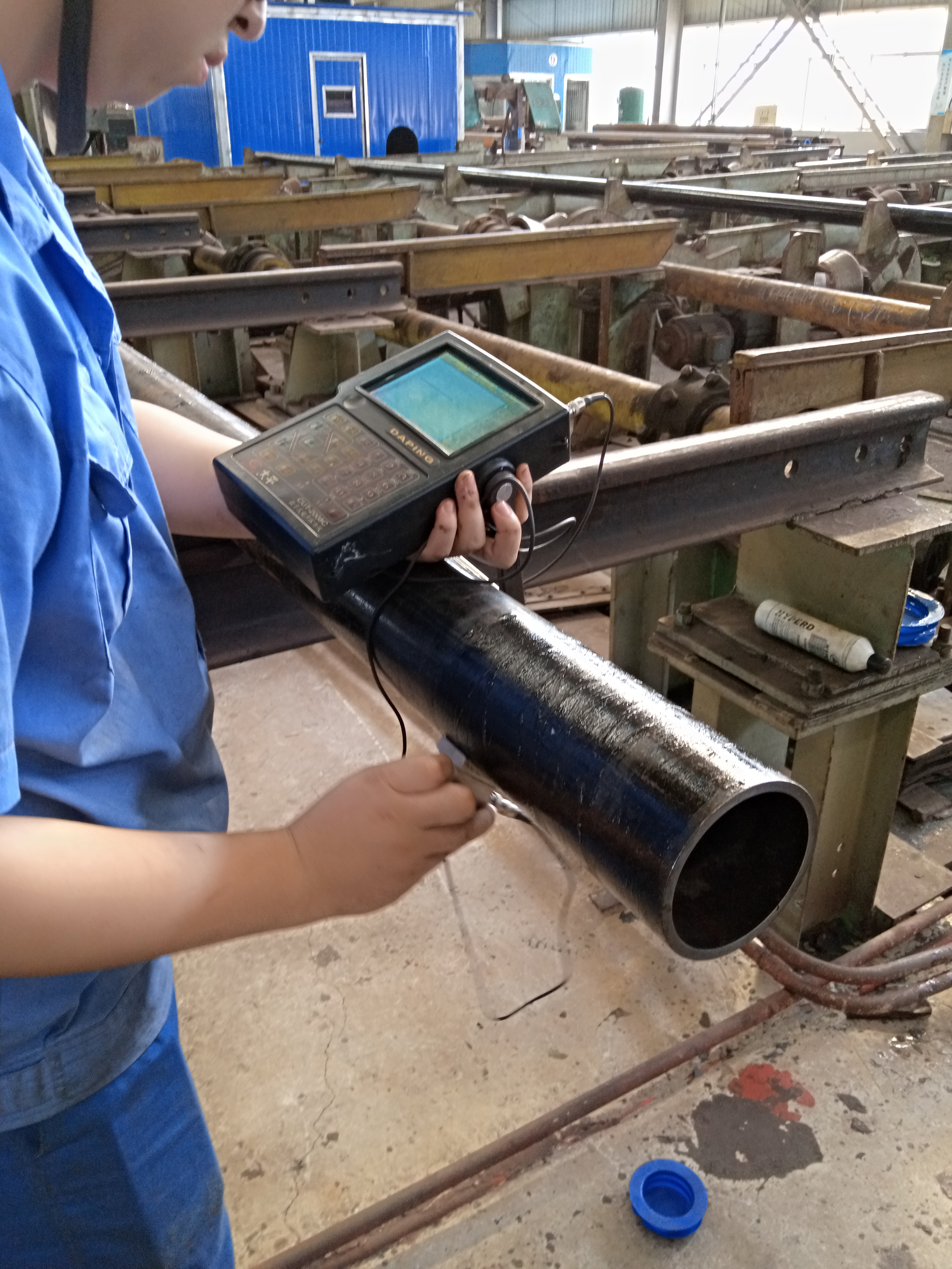
Ultrasonic inspection at the mill. Which acceptance level the equipment was calibrated to — L2 or L4 — is a function of what the purchase order says about SR 16 and SR 2, not of the equipment.
Impact testing: the lever, and why it is not free
Clause 6.5.2 covers Grades N80, R95, L80, C90, T95 and P110, taking the absorbed-energy requirement from Table 10: Cv = Ysmin × (0.00118t + 0.01259) transverse, or Ysmin × (0.00236t + 0.02518) longitudinal, "or Table C.14 / Table C.15, whichever is greater". The input is the specified minimum yield strength, so on P110 the requirement is computed from 758 MPa and its 965 MPa ceiling plays no part. That is a scoping difference worth knowing when comparing grades: 6.5.3 sends C110 and Q125 to Table 11, which uses the specified maximum yield, so those two grades carry a Charpy requirement calculated from the top of their band while P110 carries one calculated from the bottom of its.
Whether the test happens at all is separate. Clause 6.5.5 states that for grades other than C110, Q125, H40, J55 and K55, "conformance with the requirements of 6.5.2 may be qualified by a documented procedure in lieu of testing, at the manufacturer's option, unless A.9 (SR 16) is specified in the purchase agreement, in which case testing shall be performed as specified in 9.7." Table C.16 footnote a repeats it in the frequency table. Without SR 16 on the purchase order, a fully compliant P110 certificate may carry no impact results at all.
With SR 16 specified, 9.7.9 and Table C.16 put the frequency at one set of specimens per lot for pipe, across all sizes. A.16 (SR 44) — scoped to N80, L80 Type 1, L80 3Cr, C90, R95, T95, P110 and Q125 — adds a minimum percent shear area under 6.3.3, listed in Table 2. Chain that back to the previous section: SR 16 is the only lever that makes impact testing mandatory on P110, and pulling it without SR 2 relaxes the NDE acceptance level. The two belong on the same PO line.
Why the hydrostatic test pressure is capped
Clause 9.12.3, Equation (9): p = (2 × f × Ysmin × t) / D, "rounded to the nearest 0.5 MPa (100 psi) and limited to a maximum of 69.0 MPa (10,000 psi)", with f = 0.8 for P110 and for all grades other than H40, J55 and K55 above Label 1: 9⅝.
Because the equation is linear in Ysmin, the D/t at which a grade reaches the ceiling scales with its yield floor. Setting p = 69.0 MPa and solving:
- P110: D/t = 2 × 0.8 × 758 ÷ 69.0 = 17.58 — every P110 joint at or below that D/t computes above the cap
- L80: D/t = 2 × 0.8 × 552 ÷ 69.0 = 12.80
Run that against the rows each grade can actually be bought in — Table C.1 lists P110 against 43 of the 99 Table C.18 rows and L80 against 44 — and 23 of the 43 P110 rows are capped (53 %), against 4 of the 44 in L80 (9 %). Counting all 99 rows regardless of availability inflates both figures and flattens the contrast: of the 19 rows that compute above the cap in L80, all 15 that are not orderable in L80 turn out to be heavy walls Table C.1 offers in C90, T95 and C110 only. On 7″ casing, 26.00 lb/ft computes 62.69 MPa and certifies at 62.5 MPa; 29.00 lb/ft computes 70.67 MPa and certifies at 69.0 MPa, as does every heavier 7″ row Table C.1 lists P110 against. On most heavy-wall P110 the certificate pressure is therefore the ceiling, not a size-specific number, and two joints of different wall will show the same figure because both were truncated.
Annex A.13 settles whether that is a defect. Its title is "SR 41—Supplemental Inspection When Hydrostatic Test Pressure Is Limited to 69.0 MPa (10,000 psi)", and it offers two remedies when the cap binds: A.13.1 (SR 41.1), wall thickness measured and recorded over the full length with a minimum 100 % coverage of the area covered by the automatic system and the minimum measured wall recorded per length; and A.13.2 (SR 41.2), full-body imperfection NDE using oblique OD/ID reference indicators per 9.15.4 e). Clause 9.12.3 b) 1) ii) also permits an agreed alternative test pressure above 69.0 MPa. All three are Table 3 agreement items.
Where the "3,000 psi P110 test pressure" answer comes from — and why it is wrong. A figure of 3,000 psi turns up in AI-generated answers about P110 hydrostatic testing. It is a misreading of 9.12.3 b) 2) ii), which states that "the hydrostatic test equipment capability may be less than 20.5 MPa (3000 psi) only for those products where the calculated test pressure is less than 20.5 MPa (3000 psi)." That is a constraint on when a mill may operate low-capacity test equipment, not a test pressure for any grade, and P110 is the grade least likely to encounter it — on 7″ the lightest row Table C.1 lists P110 against, 26.00 lb/ft, already computes 62.69 MPa, three times the 20.5 MPa threshold. The only P110 number in 9.12.3 is the 69.0 MPa (10,000 psi) ceiling. If a supplier quotes 3,000 psi against P110, ask which clause.
Straightening: the clause where API 5CT steps back
Clause 5.3.2, "Grades H40, J55, K55, N80, R95, and P110", reads in its entirety: "No specific methods are required." It then adds one sentence: "Optional requirements for Grades R95 and P110 are specified in A.14 (SR 42)."
Set that against 5.3.3, written for L80, which prescribes a 480 °C (900 °F) minimum exit temperature for hot rotary straightening and mandatory stress relief at 480 °C minimum after cold rotary straightening; and against 5.3.4 for C90, T95 and C110, which ties the exit temperature to no more than 165 °C below the final tempering temperature. P110 — the highest-strength carbon grade below Q125 — has no such clause by default.
A.14 (SR 42) is the opt-in, scoped to Grades R95 and P110 only: 400 °C (750 °F) minimum exit temperature for hot rotary straightening, 510 °C (950 °F) minimum stress relief after cold rotary straightening, gag straightening per 5.3.6. Table 2 lists it as purchaser-specified, as "Hot rotary straightening minimum temperature—Grades L80, C90, T95, R95, P110, and Q125 · 5.3.2, 5.3.3, 5.3.5, A.14 (SR 42)". One PO line converts an unregulated process step into a specified one. Clause 5.3.1 still requires a documented procedure and 5.5 validation for cold straightening either way — but validation proves the mill's procedure repeatable; it does not impose a temperature.
Collapse: the one grade-and-size combination API 5C3 publishes
API Bulletin 5C3 works its combined-load collapse example on exactly 7″ OD, 26 lb/ft, Grade P110 — a rare case where a standard publishes a number for a specific joint rather than a formula to apply.
What API 5C3 publishes, from the Section 2.1.5 example: wall 0.362 in., D/t 19.34, axial stress 11,000 psi, Yp 110,000 psi, modified yield Ypa 104,087 psi, plastic regime, minimum collapse pressure 6,110 psi. API 5C3 is a USC document throughout; the 42.1 MPa equivalent is our conversion, not a published figure.
What computing the same formulas gives, through src/lib/pressure-formulas.ts:
- Axial correction, Formula 8: Ypa = Yp × [√(1 − 0.75 × (Sa/Yp)²) − 0.5 × (Sa/Yp)], with Sa/Yp = 11,000 ÷ 110,000 = 0.1 → Ypa = 110,000 × 0.94624 = 104,087 psi
- Boundaries at Ypa = 104,087: (D/t)_YP = 12.59, (D/t)_PT = 20.75. D/t = 19.34 falls between, so the plastic formula governs: Pp = Ypa × [A/(D/t) − B] − C with A = 3.158, B = 0.0789, C = 2,675 → 6,111 psi, matching the published 6,110 psi
- Same geometry at zero axial load, recomputed with Yp = 110,000 and its coefficients: still plastic, 6,232 psi
The gap between those last two is smaller than the folklore says. Axial tension of 11,000 psi costs about 2 % of collapse resistance — real, worth carrying in the design, and nothing like the dominant term. What dominates is regime selection: at D/t 19.34 this joint is plastic, and applying the yield-strength formula because the pipe looks thick-walled produces a number with no basis. Boundaries move with yield, so the same geometry in L80 is also plastic, at 5,411 psi. Full equations: API 5C3 calculation reference →; to check a specific D/t, use the collapse calculator →. Joint strength is a separate calculation with its own equations in API 5C3 — round-thread fracture and jump-out, coupling fracture, buttress pipe-thread and coupling-thread — and it needs the connection geometry, not just the pipe body: run it in the joint strength calculator →. For what connection test levels certify, see premium connection CAL ratings and ISO 13679 →.
Couplings, colour bands and stamp marking
P110 sits on both sides of the coupling-upgrade cascade in clause 8.2. 8.2.9: "Grades N80 Type 1 and N80Q buttress casing shall be furnished with Grade P110 couplings when specified in the purchase agreement." 8.2.10: "Grade P110 buttress casing shall be furnished with Grade Q125 couplings when specified in the purchase agreement." 8.2.8 sends P110 special clearance couplings onto N80 external-upset tubing. All three are purchase-agreement conditional — Table 2 lists "alternative grades or heat treatments of coupling" against 8.2 — so none happens by default, and under 5.1 coupling material is seamless regardless of the pipe-body route.
Table C.41 gives P110 one white band on the pipe and an entirely white coupling with no bands. Two adjacent entries matter at the rack: C110 is one white band plus two brown, on a white coupling with two brown bands, and J55 casing couplings are bright green with one white band. So a plain white coupling is P110; a white coupling with two brown bands is C110. The discriminator is the brown, not the white — and paint is the first thing transit damages. Colour marking is clause 10.4 in the 11th Edition, so a procedure or datasheet citing a §11.x clause number for colour marking is not pointing at the edition this page is written against; check which edition it was drafted to before working from it.
Stamp marking carries a P110-specific relaxation. 10.2.4 covers H40, J55, K55, N80 and P110: when specified in the purchase agreement, products are stamped by one or more of the Table 20 methods at the manufacturer's option, and nothing more. 10.2.5, covering R95, L80, C90, T95, C110 and Q125, adds mandatory heat treatment after stamping — after method 2 for R95 and L80, and after methods 2 and 4 for C90, T95, C110 and Q125, subject to the exceptions in 10.2.5 b) 1) and b) 2). P110 has no post-stamp heat-treatment requirement. The make-up triangle is the exception: 10.2.6 requires it stamped on both ends of every buttress casing length in all grades, and restricts P110 to methods 2, 3, 4 or 5 — not method 1, hot-rolled or hot-stamped.
Sour service: what API 5CT gives P110, which is nothing
API 5CT builds no sour-service controls into P110, and the scoping is explicit rather than implied. Clause 6.14 and clause 9.10 are both titled "Sulfide Stress Cracking Test—Grades C90, T95, and C110", and 6.14.1 names the same three grades: "The purchaser should refer to NACE MR0175/ISO 15156-1 and ISO 15156-2 for guidance on the usage of Grades C90, T95, and C110." A.18 (SR 46) is scoped to C90 and T95. The NOTE to 6.14.1 adds that the SSC test "is for quality control purposes only and does not qualify the material for any specific sour service application".
So on P110 there is no SSC test, no hardness ceiling, no hardness variation limit and no acceptance criterion tied to an H₂S environment. Our own data classifies P110 as general service — a ZC classification, not an API 5CT concept. Whether a given well permits P110 is decided by NACE MR0175 / ISO 15156-2, a different standard with its own limits, which this page does not restate. Run the conditions through the sour service selector → and read OCTG sour-service grade selection → before fixing a grade. Where a project specification demands an SSC result on the certificate, that requirement selects a different grade rather than a supplementary requirement: T95 → or C110 →.
Where P110 sits, and where to find the sizes
| Table C.5 | L80 (all types) | T95 | C110 | P110 | Q125 |
|---|---|---|---|---|---|
| Min yield, MPa (ksi) | 552 (80) | 655 (95) | 758 (110) | 758 (110) | 862 (125) |
| Max yield, MPa (ksi) | 655 (95) | 758 (110) | 828 (120) | 965 (140) | 1034 (150) |
| Min tensile, MPa (ksi) | 655 (95) | 724 (105) | 793 (115) | 862 (125) | 931 (135) |
| Max hardness | 23.0 HRC | 25.4 HRC | 29.0 HRC | none | none |
| Elongation under load | 0.5 % | 0.5 % | 0.7 % | 0.6 % | 0.65 % |
P110 and C110 share a yield floor and differ by 137 MPa at the ceiling — the band, not the minimum, separates them, and C110 buys that narrow band together with a hardness limit and an SSC test. The table is positional only; for the selection arguments see P110 vs L80 → and Q125 vs P110 →.
Dimensions are grade-independent — the same Table C.18 row serves every grade — but availability is not, and it lives in a different table. P110 is listed in Table C.1 against 43 of the 99 Table C.18 casing rows, from 4½″ 11.60 lb/ft (114.30 mm) to 16″ 109.00 lb/ft (406.40 mm). Column 12 of Table C.1 shows a dash on the heavy-wall tail of every size that has one — all of 5½″ 26.80 to 43.10 lb/ft, 7″ 42.70 to 57.10, 9⅝″ 59.40 to 75.60 — and on the light 7″ rows at 17.00, 20.00 and 23.00 lb/ft. The whole of 18⅝″ and 20″ is dashed, so the largest P110 casing API 5CT lists is 16″ 109.00 lb/ft: API 5CT casing sizes and weight tables →. On the tubing side, Table C.2 column 16 runs P110 from 1.050″ 1.48 lb/ft to 3½″ 12.70 lb/ft, and not in every row — every 4″ and every 4½″ row is dashed, as are 1.050″ 1.14, 1.315″ 1.70, 1.660″ 2.09 and 2.30, and 1.900″ 2.40. Note that tubing drift is specified by API 5CT, not left to the purchase order — 7.10 requires each length drift-tested throughout its entire length and Table C.23 gives the mandrel as a deduction from d (d − 2.38 mm up to Label 1: 2⅞, d − 3.18 mm above 2⅞ to 8⅝): API 5CT tubing sizes and weights →.
What we watch on P110 orders. The 9⅝″ 53.5 ppf production string is the P110 specification we quote most often — it is what went out on the 580-joint ZC-31 full-flush shipment to an African operator and again alongside a 13⅜″ L-80 string on a repeat Nigerian order. That size sits awkwardly on 9.12.3: at 13.84 mm wall its D/t is 17.66, just above the 17.58 break-even, so Equation (9) gives 68.66 MPa and the certificate reads 68.5 MPa — half a megapascal under the cap. The next row up, 58.4 ppf at 15.11 mm, computes 74.96 MPa and certifies at 69.0 MPa flat. Buyers comparing certificates across a mixed order see one string with a size-specific number and another with a round ceiling and read it as an inconsistency. It is Equation (9) doing what it says. We now put the calculated and the capped value side by side on the order acknowledgement rather than explaining it after the MTC lands.
When not to use P110
- When the project specification requires an SSC test result on the certificate. API 5CT has no SSC clause for P110 — 6.14 and 9.10 are scoped to C90, T95 and C110. That selects a grade, not a supplementary requirement; no SR fills the gap.
- When per-length or per-lot hardness data is a contractual deliverable. Table C.35 has no P110 row and 9.6.3 and 9.6.4 exclude the grade. No hardness-frequency SR is available on P110 at all; A.19 (SR 47) is C90 and T95 only.
- When the design depends on a bounded yield. Table C.5's 207 MPa (30 ksi) window is the widest of the high-strength Q+T grades, tied with N80Q and wider than Q125's 172 MPa (25 ksi) or C110's 70 MPa (10 ksi). Where over-strength matters — connection stress analysis, or brittle behaviour at a stress concentration — C110's 758–828 MPa band provides the ceiling by clause.
- When the project spec imposes a carbon or CE ceiling and the PO does not repeat it. Table C.4 restricts only P and S. A chemistry limit that lives only in the project specification will not be applied at the mill.
- When the receiving procedure has been copied from an L80 or N80 job. The transverse NDE pass, the magnetic-particle "NA" cell in Table C.37 and the absent hardness criterion all differ. Such a procedure will miss requirements and raise findings that do not exist.
- When load calculations are satisfied by a lower grade. Where N80Q or L80 carries the burst and collapse duty, the extra yield buys a wider, less predictable band and a certificate with fewer criteria on it.
Purchase order guidance
API 5CT sorts a P110 order into three levels, and the level decides whether a PO line is an obligation, an entitlement, or an opening position.
| Level | Where it lives | P110-relevant examples |
|---|---|---|
| Purchaser must supply | Table 1 (4.2.1) | Grade; seamless or electric-welded; Label 1 and Label 2; connection type; length; quantity; inspection by the purchaser (Annex B) |
| Purchaser specifies | Table 2 (4.2.2) | A.9 (SR 16) impact · A.16 (SR 44) shear area · A.14 (SR 42) straightening · A.20 (SR 48) end NDE · A.21 (SR 49) 100 % wall measurement · alternative drift (7.10) · alternative coupling grade (8.2) · traceability (5.4.1) |
| Both parties agree | Table 3 (4.2.3) | A.3 (SR 2) supplementary NDE · A.6 (SR 11) electric-weld P110 · A.13 (SR 41.1 / 41.2) when the hydrostatic cap binds · alternative hydrostatic test pressure (9.12.3) · marking requirements (10) |
The procurement trap. A purchase order line reading:
"API 5CT P110, 9⅝″ 53.50 lb/ft, BTC, R3, with SR16 for impact testing"
produces, entirely compliantly: pipe inspected to acceptance level L4 under 9.15.7 — a 12.5 % reference notch instead of the 5 % that plain P110 would have had under 9.15.8 — with no straightening temperature control (5.3.2), no post-stamp heat treatment, whatever chemistry the mill's recipe produces outside P and S, and — because Table 1's process line was left blank and 5.1 bars electric-welded P110 without A.6 (SR 11) — seamless by default, which happens to be what the buyer wanted but is not what the buyer specified. Every one of those is correct against the standard. Write instead:
"API 5CT 11th Edition, Grade P110, seamless, 9⅝″ 53.50 lb/ft, BTC, R3. Supplementary requirements: A.9 (SR 16) impact testing per 9.7 together with A.3 (SR 2), so that pipe-body NDE remains at acceptance level L2 per 9.15.8 and Table C.38; A.14 (SR 42) straightening; A.16 (SR 44) minimum percent shear area; A.21 (SR 49) wall thickness measurement, 100 % coverage. Certificate content per 12.3, including 12.3 e) minimum tempering temperature from the documented procedure, 12.3 g) specimen type, size and orientation, 12.3 h) impact acceptance criteria and individual absorbed energies, and 12.3 n) the minimum hydrostatic test pressure and duration, stated as calculated and as applied where 9.12.3 caps it."
Certificate checks, by clause
Clause 12.2 requires certification with a statement of conformance for all delivered product; 12.3 sets the content. Five lines matter most on P110. 12.3 a) — standard, edition and revision date, where an 11th Edition order gets caught being certified to the 10th. 12.3 b) — applicable SRs; if SR 16 was paid for and is not listed, no impact test was performed, because 6.5.5 made it optional. 12.3 d) — grade, process of manufacture and type of heat treatment, where the seamless-or-EW answer is recorded. 12.3 e) — the minimum tempering temperature allowed by the documented procedure: the field with no Table C.3 column value behind it on P110, and in our experience the one most likely to arrive blank where a mill runs P110 through a certificate template shared with grades that do have a column value. 12.3 n) — the minimum hydrostatic test pressure and duration, which on 23 of the 43 casing rows P110 is listed in reads 69.0 MPa because 9.12.3 truncated it. Records are retained five years under 12.4. API 5CT makes no reference to EN 10204 anywhere, so a 3.1 or 3.2 requirement is a purchase-order overlay on clause 12 — reasonable to require, not automatic. Inspection scope and total-cost modelling for a P110 string: P110 procurement and running-cost guide →.
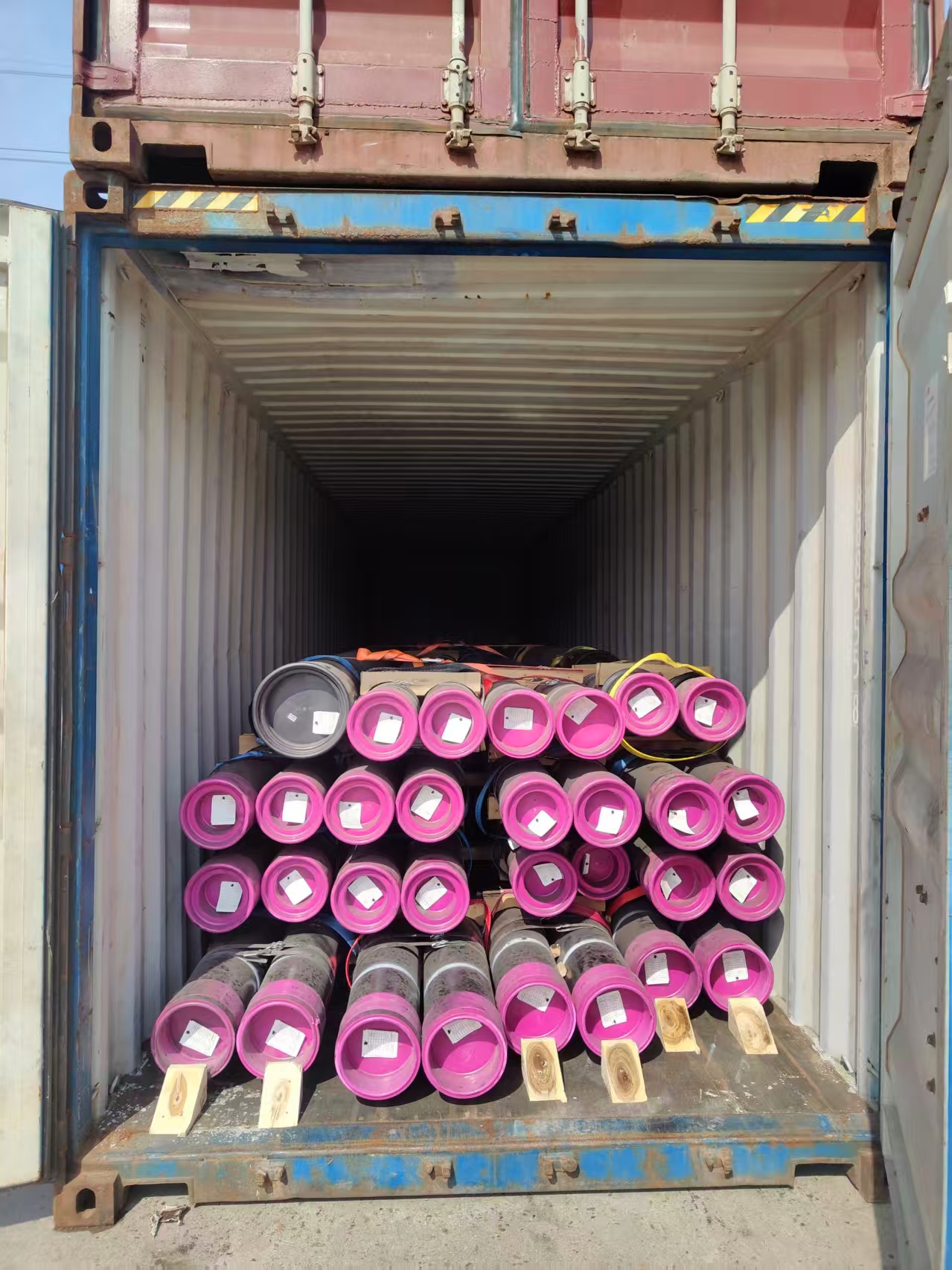
9⅝″ P-110 casing containerised for Africa, protectors fitted and every joint tagged. By this point the process route, the SR list and the NDE acceptance level are fixed and cannot be added back.
The correction we raise most often before a P110 order goes to mill is not the grade and not the size — it is the SR line. Enquiries arrive specifying SR 16 alone, usually because a project specification asks for Charpy results, and the buyer reads SR 16 as pure addition. It is not: it makes 9.7 testing mandatory and moves the pipe-body acceptance level from L2 to L4 under 9.15.7. We quote SR 16 and SR 2 as a pair and say why on the quotation, because SR 2 sits in Table 3 and needs the mill to agree — a conversation that has to happen at enquiry stage, not after the reference standard has been notched. The second most common correction runs the other way. Buyers tell us P110 "has to be seamless", and that is not what API 5CT says — Table C.3 gives S or EW, and 5.1 makes electric-welded P110 available whenever A.6 (SR 11) is agreed. A silent PO does land on seamless, so nobody is ever harmed by the belief; what they lose is the option. On projects where an EW mill is closer or better placed, that is a route worth knowing exists before the enquiry is written, and it has to be asked for, not assumed away.
Frequently Asked Questions
Does API 5CT specify a chemical composition for P110?
Barely. Table C.4 of API 5CT 11th Edition restricts only phosphorus at 0.030 % maximum and sulfur at 0.030 % maximum on Grade P110. Carbon, manganese, molybdenum, chromium, niobium, nickel, copper and silicon all show a dash, which means no limit is set — not zero. The single variation is footnote e, which applies only to electric-welded P110 and tightens phosphorus to 0.020 % and sulfur to 0.010 %. Any carbon or carbon-equivalent ceiling on a P110 order is a project-specification overlay and has to be written onto the purchase order to exist.
Can P110 casing be electric-welded instead of seamless?
Yes. Table C.3 column 3 shows the manufacturing process for P110 as S or EW. Clause 5.1 then states that electric-welded Grade P110 pipe shall be provided only when the SR in A.6 (SR 11) is specified in the purchase agreement, and Table 1 lists seamless or electric-welded among the information the manufacturer shall obtain from the purchaser. Pages that describe P110 as seamless-only are working from a rule that API 5CT does not contain.
Does ordering SR 16 on P110 change the NDE acceptance level?
Yes, and it moves in the direction most buyers do not expect. Clause 9.15.8 puts plain Grade P110 at acceptance level L2, while clause 9.15.7 puts Grade P110 to A.9 (SR 16) at acceptance level L4. Table C.39 makes the difference concrete: the L2 reference notch is 5 % of specified wall depth and the L4 notch is 12.5 %. Adding A.3 (SR 2) alongside A.9 (SR 16) returns the order to L2 under 9.15.8, so an order that specifies SR 16 for impact certificates without SR 2 has bought a looser pipe-body NDE than plain P110.
Why is my P110 hydrostatic test pressure capped?
Clause 9.12.3 calculates the standard hydrostatic test pressure from Equation (9), p = 2 × f × Ysmin × t / D with f = 0.8 for P110, rounds it to the nearest 0.5 MPa (100 psi) and limits it to a maximum of 69.0 MPa (10,000 psi). Because the equation scales with the specified minimum yield strength, P110 reaches that ceiling at any D/t at or below about 17.6. Restricted to the 43 casing rows Table C.1 actually lists P110 against, that is 23 rows — 53 % of everything you can order in the grade, against 4 of the 44 rows available in L80. Annex A.13 is titled SR 41—Supplemental Inspection When Hydrostatic Test Pressure Is Limited to 69.0 MPa (10,000 psi), so the standard treats the cap as expected rather than as a deficiency.
Does API 5CT require an SSC test on P110?
No. Clause 6.14 and clause 9.10 are both titled Sulfide Stress Cracking Test—Grades C90, T95, and C110, and the general guidance in 6.14.1 names those same three grades. P110 is outside the scope of both clauses, so no SSC test, no hardness ceiling and no sour-service acceptance criterion exists for the grade anywhere in API 5CT. Whether a given well environment permits P110 is a question for NACE MR0175 / ISO 15156-2, which is a different document with its own limits.
Does API 5CT set a minimum tempering temperature for P110?
No. Column 5 of Table C.3 is blank for P110, where R95 carries 538 °C, L80 Type 1 and 3Cr carry 566 °C, L80 9Cr and 13Cr carry 593 °C, C90 carries 621 °C and T95 and C110 carry 649 °C. Clause 12.3 e) still requires the certificate to state the minimum tempering temperature allowed by the documented procedure for each lot of quenched and tempered casing and tubing, so the figure has to come from the mill's own procedure rather than from the table. In our experience that is the field most likely to arrive blank, because a certificate template shared with grades that do carry a Table C.3 value has nothing to populate it from on P110.
What is the maximum yield strength for P110, and what happens above it?
Table C.5 sets 965 MPa (140 ksi) as the maximum yield strength for P110, against a 758 MPa (110 ksi) minimum — a 207 MPa (30 ksi) window, which is wide by API 5CT standards. Clause 6.2.3 defines that yield as the tensile stress required to produce the total elongation under load given in Table C.5, which for P110 is 0.6 %, not the 0.5 % used for H40 through L80. A heat testing above 965 MPa does not conform to Table C.5 and the material is not Grade P110, whatever else is correct on the certificate.
What straightening requirements apply to P110?
By default, none. Clause 5.3.2, covering Grades H40, J55, K55, N80, R95 and P110, reads in full: No specific methods are required. Compare clause 5.3.3, which prescribes a 480 °C (900 °F) minimum rotary-straightening exit temperature and mandatory stress relief for Grade L80. The opt-in for P110 is A.14 (SR 42), scoped to Grades R95 and P110 only, which sets the 400 °C (750 °F) exit temperature and a 510 °C (950 °F) minimum stress-relief temperature. Table 2 lists it as a purchaser-specified option, so one line on the purchase order buys a residual-stress control the grade otherwise has none of.