Casing design sits at the intersection of drilling engineering and procurement. The drilling engineer computes loads; the procurement engineer sources the pipe to resist them. When these two functions are separated — as they commonly are in EPC contracts — errors enter the material requisition. A production casing specified as "P110, 7 inch, 26 lb/ft, BTC" passes through procurement without anyone noticing that the well has 800 ppm H₂S at depth, and that P110 is not qualified for sour service.
ZC Steel Pipe supplies casing to drilling programmes across sub-Saharan Africa, the Middle East, and Southeast Asia. The most expensive MRQ mistakes we see are grade errors on the production string and connection selection errors on deviated wells — both recoverable before manufacturing, neither recoverable once the string is run. This guide follows the design sequence from top to bottom.
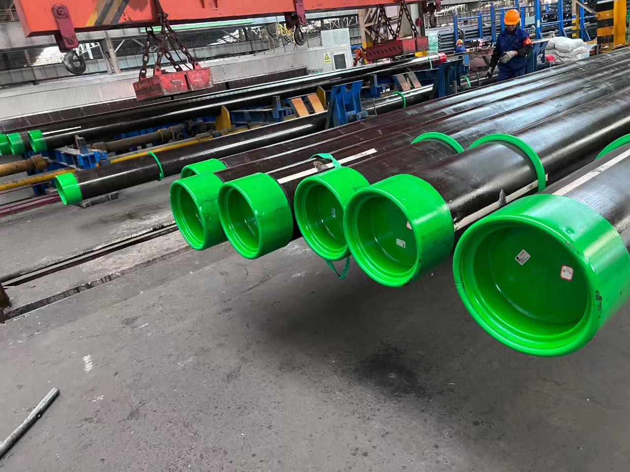 ZC casing with green couplings and thread protectors on the production line — part of a K55 BTC casing string supplied to a Middle East operator.
At a Glance — The Design Sequence
Casing design runs top-down: size each string, compute its three load cases (collapse, burst, tension), then pick the lowest-cost grade that covers the governing load at the project design factor. The table below maps each string to its typical grade and the load that usually controls it.
| String | Typical OD | Typical grade | Usually governed by |
|---|---|---|---|
| Conductor | 20–36 in | J55 / K55 | Compression — wellhead weight |
| Surface | 13⅜–16 in | J55 / K55 / N80-1 | Shallow collapse / burst |
| Intermediate | 9⅝–10¾ in | N80 / L80 / P110 | Collapse at depth |
| Production | 7 / 5½ in | N80Q or P110 (sweet) · L80 / T95 / C110 (sour) | Burst at wellhead or collapse at shoe |
The single most expensive decision is production-string grade. Sweet wells run N80Q or P110; the moment H₂S is present the grade must be qualified under NACE MR0175 / ISO 15156-2 (L80-1, T95, or C110), and P110 is disqualified regardless of PO language. Everything below walks the calculation that produces these choices.
The Four Standard Casing Strings
A conventional vertical or near-vertical well uses four strings of casing, each serving a different structural and pressure-isolation function. The programme may collapse to three strings (eliminating the intermediate) on shallow sweet wells, or expand to five on HPHT deepwater wells.
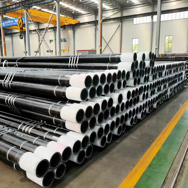 Finished casing bundled by weight under an overhead crane in the ZC mill, ready for coupling make-up and load-out.
Conductor Pipe
Size: typically 20–36 inches OD. Set depth: 30–150 m. Function: structural support for the wellhead and surface equipment, protection against shallow washout and gas migration. Conductor is usually driven or jetted — rarely rotated — and cemented from shoe to surface. Grade is typically J55 or K55; dimensional tolerance is less critical than for deeper strings because loads are primarily vertical compression from wellhead weight. Connections are commonly STC (short thread coupling) or plain end with field welding.
Surface Casing
Size: typically 13-3/8 or 16 inches OD. Set depth: 300–600 m. Function: fresh water zone isolation (regulatory requirement in most jurisdictions), structural support for the BOP stack, blowout prevention through its rated working pressure. Surface casing must be cemented to surface and pressure-tested. Grade is typically J55, K55, or N80-1, depending on shallow collapse and burst requirements. If a shallow gas zone exists above the kick-off point, N80Q adds collapse resistance without requiring premium connections.
Intermediate Casing
Size: typically 9-5/8 or 10-3/4 inches OD. Set depth: variable — run as needed to case off abnormally pressured zones, lost circulation intervals, or unstable shales. Intermediate casing may be eliminated if the pore pressure gradient is consistent from surface to reservoir. Grade is driven by collapse at depth and burst at the wellhead: N80, L80, or P110 are the typical range. Sour service gas caps above the reservoir may require L80-1 even on an intermediate string.
Production Casing
Size: typically 7 or 5-1/2 inches OD. Set depth: reservoir. Function: primary pressure barrier for the life of the well. This is the string where grade selection matters most, because it is exposed to the full reservoir pressure and temperature during production. The design load analysis below uses the production string as the worked example.
The Three Design Load Cases
Casing is designed against three independent load conditions. The governing load — the one that controls grade and weight selection — varies by string position and well type. For a first-principles refresher on each mode, see casing design basics — collapse, burst and tension.
Collapse
Definition: External pressure minus internal pressure. Collapse governs when the pipe interior is at lower pressure than the formation fluid acting externally.
Critical scenario: The production string collapses if formation pressure is high and the casing is depleted or lost circulation fluid is replaced by gas. For the design case, most operators use full evacuation — zero internal pressure — with external load equal to the estimated pore pressure gradient at the shoe. This is conservative; some operators use a partial evacuation scenario if the well will not experience full evacuation in its life.
API 5C3 collapse formula regime: The applicable formula (yield-strength, plastic, transition, or elastic) is selected based on the D/t ratio. For 7-inch 26 lb/ft casing (OD = 7.0 in, wall = 0.362 in), D/t = 7.0 / 0.362 = 19.34.
For N80Q (Grade L-N-80 in API 5C3):
- D/t boundaries from API 5C3: (D/t)_YP = 13.38, (D/t)_PT = 22.47, (D/t)_TE = 31.02
- D/t = 19.34 falls between (D/t)_YP and (D/t)_PT → plastic collapse regime
Plastic formula: Pp = Yp × [A / (D/t) − B] − C
Using L-N-80 coefficients from API 5C3 (A = 3.071, B = 0.0667, C = 1,955): Pp = 80,000 × [3.071 / 19.34 − 0.0667] − 1,955 = 80,000 × [0.1589 − 0.0667] − 1,955 = 80,000 × 0.0922 − 1,955 = 7,376 − 1,955 = 5,421 psi (37.4 MPa)
This is the minimum collapse resistance of 7-inch 26 lb/ft N80Q before axial load correction. An axial tension load in the string will reduce this value further — use the axial stress correction formula in API 5C3 Section 2.1.5 for the actual string. To run the regime selection and collapse formula for any size and grade, use the collapse pressure calculator; the full coefficient set is on the API 5C3 / Bulletin 5C3 reference.
Burst
Definition: Internal pressure minus external pressure. Burst governs when reservoir fluid enters the casing at high pressure while the external annulus fluid pressure is low.
Critical scenario: Gas kick at the wellhead with full shut-in surface pressure. Burst pressure at the wellhead = shut-in wellhead pressure (SIWHP). For a well with 690 bar (10,000 psi) BHSIP, 4,500 m TVD, and a gas gradient of 0.1 psi/ft, SIWHP ≈ 10,000 − (0.1 × 4,500 × 3.281) = 10,000 − 1,476 = 8,524 psi (587 bar) at the wellhead. This is the burst load the production casing must resist at the shoe-to-wellhead section.
Minimum burst resistance (API 5C3): For 7-inch 26 lb/ft N80Q:
Pb = 0.875 × 2 × Yp × t / D = 0.875 × 2 × 80,000 × 0.362 / 7.0 = 0.875 × 8,274 = 7,240 psi (49.9 MPa)
N80Q at 7" 26 lb/ft does not meet the burst requirement for a well with 590 bar SIWHP at the wellhead. The calculation tells you to step up to a heavier weight or higher grade.
For P110 at 7" 26 lb/ft (same wall 0.362"): Pb = 0.875 × 2 × 110,000 × 0.362 / 7.0 = 0.875 × 11,377 = 9,955 psi (68.6 MPa) ✓ — meets the burst requirement with a safety factor of 9,955 / 8,524 = 1.17.
Check burst ratings for other sizes and grades with the Barlow pressure calculator.
Tension
Definition: Axial tension load from the weight of the string in air, adjusted for buoyancy in drilling fluid, plus overpull. Tension governs typically at the top of the string.
Minimum tensile resistance (pipe body yield): T = Yp × A_s
Where A_s = cross-sectional area of pipe wall.
For 7-inch 26 lb/ft: A_s ≈ 7.549 in² (from API 5CT tables)
N80Q pipe body yield tension: T = 80,000 × 7.549 = 603,920 lbf (2,686 kN) P110 pipe body yield tension: T = 110,000 × 7.549 = 830,390 lbf (3,694 kN)
String weight in 14 ppg mud at 4,500 m (14,764 ft): approx. 26 × 14,764 × (1 − 14/65.4) ≈ 26 × 14,764 × 0.786 ≈ 301,730 lbf
Design tension = string weight + overpull (typically 100,000 lbf). For P110, design tension safety factor = 830,390 / (301,730 + 100,000) = 830,390 / 401,730 = 2.07 — well above the typical minimum of 1.6.
Grade Selection by String
Numbers from api-5ct-spec.json — API Specification 5CT, 11th Edition.
| Grade | Min Yield (MPa/ksi) | Max Yield (MPa/ksi) | Max HRC | Sour Service | Heat Treatment | Typical String |
|---|---|---|---|---|---|---|
| H40 | 276/40 | 552/80 | None | No | As-rolled | Conductor |
| J55 | 379/55 | 552/80 | None | No | Normalised | Conductor, Surface |
| K55 | 379/55 | 552/80 | None | No | N+T | Surface |
| N80-1 | 552/80 | 758/110 | None | No | N or N+T or Q+T | Intermediate |
| N80Q | 552/80 | 758/110 | None | No | Q+T only | Intermediate |
| L80-1 | 552/80 | 655/95 | 23 | Yes | Q+T only | Production — mild sour |
| R95 | 655/95 | 758/110 | None | No | Q+T | Intermediate |
| C90 | 621/90 | 724/105 | 25.4 | Yes | Q+T only | Production — moderate sour |
| T95 | 655/95 | 758/110 | 25.4 | Yes | Q+T only | Production — sour deep |
| C110 | 758/110 | 828/120 | 29 | Yes | Q+T only | Production — severe sour |
| P110 | 758/110 | 965/140 | None | No | Q+T only | Production — deep HPHT sweet |
| Q125 | 862/125 | 1,034/150 | None | No | Q+T only | Ultra-deep HPHT sweet |
Two values in this table drive most grade errors: the Max HRC column and the Sour Service flag.
P110 has no hardness limit under API 5CT. A mill can ship P110 at HRC 26 and be fully compliant. NACE MR0175 / ISO 15156-2 requires carbon steel OCTG in H₂S service to not exceed HRC 22. These two facts together mean that P110 — the grade most commonly used for deep wells — cannot be qualified for sour service. There is no PO language that converts P110 into a sour-service grade.
P110 in sour wells: P110 is not qualified for H₂S service under NACE MR0175 / ISO 15156-2. Its maximum yield of 965 MPa (140 ksi) produces hardness levels that routinely exceed HRC 22 in the heat-affected zone. Do not specify P110 for any string exposed to H₂S partial pressure above the threshold in ISO 15156-2 Table 1. The correct high-strength sour grade is C110 (max HRC 29, API 5CT qualified sour).
For the complete API 5CT mechanical property and hardness tables, see API 5CT specification tables →
To match well conditions to grade, use the Pipe Grade Selector →
Worked Design Example — 7-Inch Production String, HPHT Sweet Well
Well parameters:
- TVD: 4,500 m (14,764 ft)
- BHSIP: 690 bar (10,000 psi)
- BHST: 145°C (293°F)
- H₂S: 0 ppm (sweet)
- Mud weight: 14 ppg (1.68 sg)
- Design factors: collapse 1.0, burst 1.1, tension 1.6
Candidate grade: P110, 7" 26 lb/ft (OD 177.8 mm, wall 9.19 mm)
From the calculations above:
| Load | Minimum Resistance | Required with DF | P110 Resistance | Governs? |
|---|---|---|---|---|
| Collapse | — | ≥ Pext (at shoe, full evacuation) | 6,232 psi | Check |
| Burst | — | ≥ 8,524 × 1.1 = 9,376 psi | 9,955 psi | ✓ passes with 1.06 margin |
| Tension | — | ≥ 401,730 × 1.0 | 830,390 lbf | ✓ passes with 2.07 margin |
Collapse check: external pore pressure at 4,500 m in 14 ppg formation fluid ≈ 14 × 4,500 × 0.052 × 0.433 ≈ 1,424 psi; full-evacuation collapse load ≈ 1,424 psi. P110 at 6,232 psi comfortably exceeds this. Governs on burst.
Conclusion: 7-inch 26 lb/ft P110 with BTC connection is structurally adequate for this sweet HPHT well. If the well had H₂S at depth, the grade would shift to C110 for the production string — the geometry (7" 26 lb/ft) would remain the same. For the full P110 grade, hardness and HPHT detail behind this choice, see API 5CT P110 casing specifications.
What we see on production string orders: A common MRQ pattern for HPHT wells is specifying P110 for the production string and T95 for the intermediate — the customer knows T95 is a sour-capable grade and treats it as "premium." But T95 has a lower yield (655 MPa min vs P110's 758 MPa min) and lower burst resistance. In a deep HPHT sweet well, using T95 on the intermediate to "be safe" while running P110 on the production string makes the sour designation irrelevant and adds cost without structural benefit. The correct approach is P110 throughout a sweet HPHT well, and the appropriate sour-rated grade only on strings that actually encounter H₂S.
Sour Service — What Changes in the Design
When H₂S partial pressure exceeds the threshold in NACE MR0175 / ISO 15156-2 Table 1, the grade selection constraint shifts from yield strength to hardness:
- L80-1: 552–655 MPa yield, max HRC 23 → mild sour service (H₂S moderate, CO₂ low)
- C90: 621–724 MPa yield, max HRC 25.4 → moderate sour service
- T95: 655–758 MPa yield, max HRC 25.4 → moderate-to-severe sour service
- C110: 758–828 MPa yield, max HRC 29 → severe sour service
The hardness limits are process guarantees, not just targets. API 5CT Section 10.7 requires a minimum of five hardness readings per pipe for Group 2 sour grades (L80-1, C90, T95, C110). A shipment where any reading exceeds the grade limit must be rejected regardless of tensile test results.
The procurement implication: sour service strings require additional MTC documentation. An MTC that includes tensile test data but omits the hardness survey is not acceptable for sour service grade acceptance. Check the hardness survey before clearing a sour service heat from the mill.
Connection Selection for the Production String
The connection selection follows the load analysis:
BTC (buttress thread coupling): Adequate for straight or low-deviation (<30° inclination) sweet wells within 7-inch and smaller production strings. API 5CT BTC is the default when combined load envelope calculations show the connection is not the limiting factor.
Premium connection: Required when any of the following apply:
- Deviated well (inclination >30°) where bending adds to axial load
- HPHT well where combined pressure and temperature cycling stresses the makeup
- Gas-tight requirement where thread compound seal is insufficient for sustained gas pressure
- Q125 or C110 grade, where the pipe body strength makes BTC the limiting element of the string
Connection selection must be verified against the full combined load envelope. A connection rated to API 5C5 CAL IV has been tested at the full combination of tension, compression, internal pressure, external pressure, and bending simultaneously — not each load independently. To compare API round-thread and buttress joint-strength ratings against the pipe body tension for a given size, use the joint strength calculator.
Purchase Order Guidance
Procurement traps
Trap 1 — Grade not matching service conditions. The most common MRQ error is specifying P110 for a well with low-level H₂S. The correct grade for that combination is C110 (the highest-strength sour-qualified grade) or T95 depending on the calculated load. P110 cannot be made sour-compatible.
Trap 2 — Not specifying PSL level. A PO that reads "7-inch 26 lb/ft P110 BTC" without PSL level defaults to PSL-1. PSL-1 does not require Charpy impact testing for P110 and does not mandate the same NDE scope as PSL-2. For HPHT production strings, specify PSL-2 and the required supplementary requirements (SR2 for Charpy at project temperature, if applicable).
Trap 3 — Wrong MTC specification for sour service. Sour service casing requires EN 10204 3.2 (third-party witnessed) on most projects. An EN 10204 3.1 certificate is mill-issued and does not include independent hardness verification. For any string exposed to H₂S, require 3.2 and name the TPI (SGS, Bureau Veritas, or project-specified).
Field receipt checklist
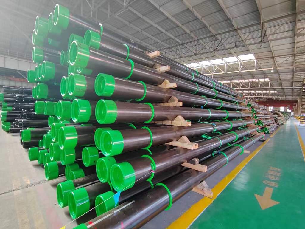 Green thread-protector-capped casing racked on wooden dunnage — the condition to verify on receipt: protectors intact and sealing surfaces undamaged.
- Verify grade and weight against the MRQ — read the pipe body stencil, not just the packing list
- For sour grades, confirm hardness survey is included in the 3.2 MTC packet and that no reading exceeds the grade limit
- Thread protectors intact; no thread compound contamination from shipping
- End bevel condition — no nicks or damage to sealing surfaces, especially for premium connections
- Measure OD and wall thickness on at least 5% of pipes per heat (more for premium connections)
- Verify tally — pipe count, total length, and length range against PO
For sour service grade selection and H₂S partial pressure thresholds, see the Sour Service Grade Selector → and the OCTG Sour Service Grade Selection Guide →
Frequently Asked Questions
What are the four casing strings in a typical oil or gas well?
A typical well uses four casing strings: conductor pipe (30–36 inches OD, driven or jetted to 30–100 m to support the wellhead and prevent surface collapse), surface casing (13-3/8 or 16 inches OD, cemented to 300–600 m to isolate fresh water zones and contain blowout), intermediate casing (9-5/8 or 10-3/4 inches OD, run as needed to isolate abnormally pressured zones), and production casing (7 or 5-1/2 inches OD, the primary pressure barrier from reservoir to wellhead).
What is the collapse load on a casing string?
Collapse load is the difference between external pressure and internal pressure acting on the pipe wall. The worst case occurs when the casing is empty (full evacuation) and fully loaded with formation fluid pressure externally — for example, a gas migration event that creates external hydrostatic pressure while the casing is gas-cut internally. API 5C3 / ISO 10400 provides collapse pressure formulas for yield-strength, plastic, transition, and elastic regimes depending on the D/t ratio of the pipe.
How do EPC engineers select casing grade for the production string?
Production casing grade is selected by comparing the maximum load case (usually either collapse at the shoe or burst at the wellhead) against the grade's minimum resistance. For sweet wells, N80Q or P110 covers most depth ranges. For sour service (H2S present), the grade must be qualified under NACE MR0175 / ISO 15156-2 — common choices are L80-1, T95, or C110. Q125 is reserved for ultra-deep HPHT wells where P110 is insufficient.
What design factors are used in casing design?
API 5C3 sets the minimum collapse safety factor at 1.0, minimum burst at 1.0, and minimum tension at 1.0, meaning the pipe must meet or exceed the load with no margin. In practice, operators apply project-specific design factors: collapse typically 1.0–1.125, burst typically 1.0–1.1, and tension typically 1.6–2.0 to account for overpull during stuck pipe events. The governing standard is usually the company's well design manual or NORSOK D-010 for North Sea projects.
What is the difference between burst and collapse on a casing string?
Burst occurs when internal pressure exceeds external pressure and the pipe wall cannot contain the difference — the pipe expands and ruptures outward. Collapse occurs when external pressure exceeds internal pressure — the pipe buckles inward. Both are governed by API 5C3 formulas, but the governing scenario differs by string position and well operation phase. Collapse typically governs production casing at depth during a full-evacuation scenario; burst typically governs at the wellhead during a shut-in with high reservoir pressure.
Can P110 be used in sour service wells?
No. P110 is not qualified for sour service under NACE MR0175 / ISO 15156-2 because its high yield strength (minimum 758 MPa, maximum 965 MPa) produces hardness levels that can exceed the ISO 15156-2 HRC 22 limit for carbon steel in H2S service. API 5CT does not set a hardness limit for P110. For high-strength sour service wells, the correct grade is C110 (max HRC 29, qualified sour service) or T95 (max HRC 25.4, qualified sour service).
What connection type should be specified for the production casing?
For straight, non-sour wells, BTC (buttress thread coupling) is the industry standard for production casing in most size ranges. For HPHT wells, deviated or horizontal wells with combined bending and pressure loads, and gas wells requiring gas-tight sealing, a premium connection qualified to API 5C5 CAL IV is required. The connection selection must cover the full combined load envelope — axial tension, compression, internal pressure, external pressure, and bending — not just individual loads.
What MTC documentation should EPC engineers require for casing?
EPC engineers should require EN 10204 3.1 as a minimum, which is a mill-issued certificate based on specific testing of the delivered product. For most international projects, EN 10204 3.2 (third-party witnessed inspection) is required for intermediate and production strings. The MTC must include heat number, chemical analysis (heat and product), mechanical test results (tensile, hardness per grade), hydrostatic test record, dimensional check, and for sour service grades a hardness survey per API 5CT 10.7.