
A 2⅞″ L80 tubing string is 73.02 mm (2.875 in.) outside diameter in six API 5CT masses from 6.4 to 11.5 lb/ft, and the one most wells run is the lightest — 6.4 lb/ft non-upset (6.5 lb/ft external-upset), 5.51 mm wall, 62.00 mm (2.441 in.) inside diameter, and a standard drift of 59.62 mm (2.347 in.). The size is fixed by the completion and the grade is fixed by the service. Two decisions are left, and no datasheet makes either of them: which coupling the annulus will accept — 88.90 mm non-upset, 93.17 mm external-upset regular, or 87.88 mm external-upset special clearance — and whether the string will actually pass the drift test, which API 5CT makes a stricter test on tubing than on casing. The full size ladder across every tubing OD lives in the API 5CT tubing sizes and selection guide →; this page is only about the 2⅞″ L80 combination and the two calls it forces.
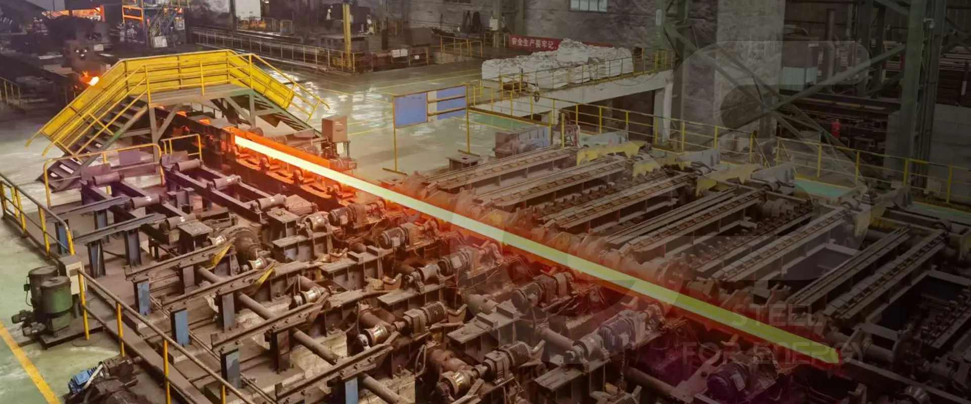
ZC Steel Pipe supplies API 5CT tubing from 1.050″ to 4½″ and casing from 4½″ to 20″, seamless and electric-welded, into West and North Africa, the Middle East, South America and Southeast Asia.
What we see on 2⅞″ orders: the most common incomplete tubing enquiry at this size reads "2⅞ L80 EUE, Range 2" — no mass and no coupling class. Both gaps are quotable and both get filled by the mill's standard: 6.5 lb/ft and a regular coupling. That is usually right, and when it is wrong it is wrong at the rig, not on the certificate. Couplings are also a separate manufacturing line from the pipe, which is why they arrive on their own pallets with their own labels — on a South American order for 15,000 API 5CT couplings in EU and LTC forms the coupling specification was pinned down independently of the pipe, and that is the habit worth copying. We ask for mass, end finish and coupling class before quoting a 2⅞″ string.
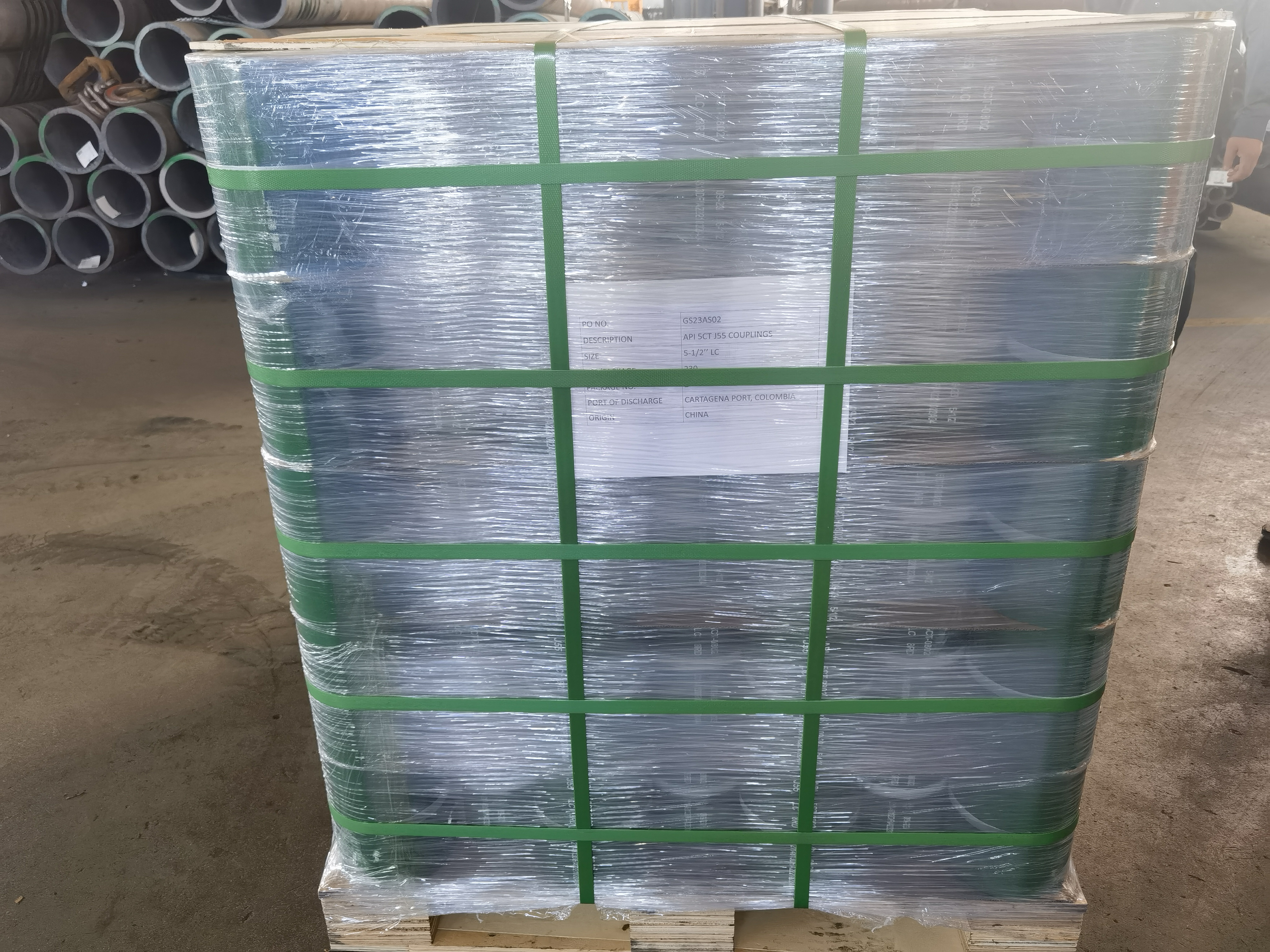 A palletised ZC coupling shipment labelled in English with PO number, description, size and port of discharge — couplings ship as their own line item, which is why they need their own specification.
At a Glance: the 2⅞″ L80 Decision
Masses and wall thickness below are API 5CT 11th Edition Table C.2. Inside diameter and plain-end mass come from Table C.19, which is the table that carries those two columns — Table C.2 has neither. The drift is computed from Table C.23 as ID − 2.38 mm. The last column is Table C.2’s per-grade end-finish column read at L80: P = plain-end, N = non-upset T&C, U = external-upset T&C.
| Mass NU / EU (lb/ft) | Mass NU / EU (kg/m) | Wall (mm / in) | ID (mm / in) | Standard drift (mm / in) | Plain-end mass (kg/m / lb/ft) | End finish offered in L80 |
|---|---|---|---|---|---|---|
| 6.4 / 6.5 | 9.52 / 9.67 | 5.51 / 0.217 | 62.00 / 2.441 | 59.62 / 2.347 | 9.17 / 6.16 | PNU — plain, NU, EU |
| 7.8 / 7.9 | 11.61 / 11.76 | 7.01 / 0.276 | 59.00 / 2.323 | 56.62 / 2.229 | 11.41 / 7.67 | PNU — plain, NU, EU |
| 8.6 / 8.7 | 12.80 / 12.95 | 7.82 / 0.308 | 57.38 / 2.259 | 55.00 / 2.165 | 12.57 / 8.45 | PNU — plain, NU, EU |
| 9.35 / 9.45 | 13.91 / 14.06 | 8.64 / 0.340 | 55.74 / 2.194 | 53.36 / 2.101 | 13.72 / 9.22 | PU — plain or EU only |
| 10.5 / — | 15.63 / — | 9.96 / 0.392 | 53.10 / 2.091 | 50.72 / 1.997 | 15.49 / 10.41 | P — plain-end only |
| 11.5 / — | 17.11 / — | 11.18 / 0.440 | 50.66 / 1.994 | 48.28 / 1.901 | 17.05 / 11.46 | P — plain-end only |
Two columns do the work. The drift, not the ID, is what a tool has to pass, and the gap between them is a fixed 2.38 mm at every mass here — a 6.4 lb/ft joint that gauges 2.441 in. still only guarantees 2.347 in. of clear bore. And the plain-end mass is not the ordered mass: 9.17 kg/m against a 9.52 kg/m NU designation, because the designation includes threads and coupling. Grade sets none of this — L80, N80Q and P110 at 6.4 lb/ft are dimensionally identical — which is why grade has to be read separately, against the pressure ratings.
The last column is the one that catches people, and the reason is a genuine trap in the layout of Table C.2. The table’s mass columns are headed "Non-upset T&C" and "Ext. Upset T&C", so a nominal non-upset mass is printed at 9.35, 10.5 and 11.5 lb/ft — 15.63 kg/m and 17.11 kg/m are right there on the page. But the mass columns only tell you what a mass would be; the per-grade end-finish column is what says which finishes are actually offered, and in L80 it reads PU at 9.35 and P at 10.5 and 11.5. None of those three masses can be ordered as a non-upset threaded-and-coupled joint in this grade.
The rating-basis error. Single-SKU tubing datasheets routinely publish 2⅞ 6.50 L80 as roughly 8,000 psi collapse, 9,660 psi burst and 114,080 lb body yield, under headings such as "Performance Ratings (New Pipe)". Those are inspection-class ratings computed on a remaining body wall, not on the full nominal wall — a used-pipe basis, not a new-pipe one. Computed on API 5C3 for new pipe at L80's 552 MPa (80 ksi) minimum yield, the same joint gives 11,160 psi collapse, 10,560 psi internal yield and 145,000 lbf body yield (5C3 rounds internal yield to the nearest 10 psi and body yield to the nearest 1,000 lbf). Against those, the published burst is 8.6 % lower and the published body yield 21 % lower. Neither set is wrong; they answer different questions. What is wrong is designing a new string against an inspection-class table, or accepting used pipe against a new-pipe one — so state the basis on the design sheet before you state the number.
Worked ratings — 2⅞″ 6.5 lb/ft L80, new pipe, API 5C3. D = 73.02 mm, t = 5.51 mm, so D/t = 13.25 and Y_p = 552 MPa (80 ksi). Internal yield: P = 0.875 × 2 × Y_p × t / D = 0.875 × 2 × 80,000 × 5.51 / 73.02 = 10,564 psi raw, which API 5C3 rounds to the nearest 10 psi: 10,560 psi (72.8 MPa). The 0.875 factor applies API 5CT's 12.5 % negative wall tolerance. Collapse: at D/t = 13.25 this joint falls in the yield-strength collapse regime, not the plastic regime, so P = 2 Y_p (D/t − 1)/(D/t)² = 11,162 psi raw, 11,160 psi (77.0 MPa) to the nearest 10 psi; using the plastic formula here would be applying it outside its range. Pipe-body yield: Y_p × π/4 × (D² − d²) = 80,000 × π/4 × (2.875² − 2.441²) = 144,962 lbf raw, which API 5C3 rounds to the nearest 1,000 lbf: 145,000 lbf (645 kN). Reproduce these for any mass with the Barlow pressure calculator → and the four-regime collapse model →.
The Coupling Decision: NU, EU Regular, or EU Special Clearance
What changes at 2⅞
| API 5CT Table C.29 / C.30 | NU regular | EU regular | EU special clearance |
|---|---|---|---|
| Coupling OD W | 88.90 mm (3.500 in.) | 93.17 mm (3.668 in.) | 87.88 mm (3.460 in.) |
| Minimum length NL | 130.18 mm | 133.35 mm | 133.35 mm |
| Width of bearing face, regular | 4.76 mm | 5.56 mm | not tabulated |
| Max bearing-face diameter Bf, special bevel | 80.98 mm | 85.88 mm | 83.24 mm |
| Coupling mass | 2.34 kg | 2.40 kg | 1.55 kg |
| Tolerance on OD | ±1 % | ±1 % | ±0.38 mm |
The bore is the same in all three cases — 62.00 mm ID and 59.62 mm drift on a 6.4/6.5 lb/ft joint — so the coupling choice buys nothing inside the string and costs only on the outside of it. Note the tolerance row: the special clearance diameter carries a tight ±0.38 mm band rather than the ±1 % that applies to regular couplings, because the whole point of that coupling is a diameter someone downhole is relying on. At 93.17 mm, ±1 % is ±0.93 mm, and that band has to go into the clearance sum.
"8RD" is ambiguous at 2⅞. Non-upset tubing at this size is 10 threads per inch (API 5B Table 6); external-upset tubing is 8 threads per inch (API 5B Table 7). Both get called round thread and both get written "8RD" on purchase orders out of habit. A PO reading "2⅞ L80 8RD" without an explicit NU or EUE end finish does not identify a thread form, and the two are not interchangeable — the pin, the coupling and the gauges are all different. Write the end finish, not the thread shorthand.
The annulus check is against casing drift, not casing ID
Coupling clearance is calculated against the casing drift, because the drift is what the casing string is guaranteed to pass along its full length; the ID is a nominal number that no tool is entitled to rely on. The two differ by 3.18 mm at every casing size from 4½″ to 8⅝″, which is 1.59 mm per side — small in absolute terms and large relative to the gaps that matter here. Casing drift values below are from the API 5CT casing size and weight tables →.
| Production casing | Casing drift | EU regular (93.17 mm) radial gap | EU special clearance (87.88 mm) radial gap |
|---|---|---|---|
| 7″ 26 lb/ft | 156.24 mm (6.151 in.) | 31.5 mm | 34.2 mm |
| 5½″ 20 lb/ft | 118.18 mm (4.653 in.) | 12.5 mm | 15.2 mm |
| 4½″ 13.5 lb/ft | 96.38 mm (3.794 in.) | 1.61 mm | 4.25 mm |
| 4½″ 15.1 lb/ft | 94.00 mm (3.701 in.) | 0.42 mm | 3.06 mm |
Inside 7″ casing the question does not arise: an EU regular coupling leaves 31.5 mm per side and the decision is made on strength and cost alone. Inside 5½″ it is comfortable but no longer free — and note that running the same sum against the 5½″ 20 lb/ft ID of 121.36 mm returns 14.1 mm instead of 12.5 mm, overstating the gap by 1.59 mm. Inside 4½″ the arithmetic decides the order: at 13.5 lb/ft an EU regular coupling has 1.61 mm per side nominal, and applying the +1 % tolerance to the coupling (94.10 mm) cuts that to 1.14 mm; at 15.1 lb/ft the nominal gap is 0.42 mm per side while the coupling tolerance alone is ±0.93 mm diametral, which is to say the clearance is inside the manufacturing band and cannot be relied on at all. Check the number against your own minimum for the running conditions — debris tolerance, casing ovality, control lines in the annulus — rather than against a generic rule.
What special clearance costs you
Two things, both in Table C.30. The bearing face narrows: the maximum special-bevel bearing-face diameter falls from 85.88 mm to 83.24 mm, so the shoulder that reacts make-up torque and any compressive load is smaller. And the coupling mass falls from 2.40 kg to 1.55 kg, which is the metal that came off. Coupling class is a purchaser election in its own right, not a consequence of the end finish: API 5CT Table 4 — Purchaser-supplied Information (Tubing) lists "Regular couplings with special bevel NU, EU" and "Special clearance couplings—EU" as two separate items the manufacturer must obtain from the purchaser, alongside the end finish and the mass. Special clearance is also not available everywhere: API 5CT lists a special-clearance diameter at 2⅜, 2⅞ and 3½ tubing, and the column is blank at 4 and 4½ — so a clearance problem at those larger sizes is solved by a premium connection or a smaller string, not by a special-clearance API coupling.
"NU for clearance, EU for strength" is a false choice at 2⅞. The stock framing assumes the non-upset coupling is the slim one. It is not. An EU special-clearance coupling is 87.88 mm (3.460 in.) — 1.02 mm smaller in diameter than the 88.90 mm (3.500 in.) NU regular coupling — while still giving you the upset pin, where the thread is cut into thickened metal instead of into the pipe wall. The bore is identical either way: 62.00 mm ID, 59.62 mm drift. So on a tight 4½″ annulus the right question is not "do we drop to NU for clearance" but "do we specify EU special clearance and keep the upset". You pay in bearing face and coupling mass, not in inside diameter.
For the upset mechanism, see the EU and NU tubing connection guide →; for coupling grades and marking, the API 5CT coupling guide →. One caution on connection strength: any numeric EU-versus-NU joint rating quoted to you should be traced back to the document and edition it came from before it enters a design, because the same size and mass is published with different joint-strength numbers by different sources. The API 5C3 formulas → are the reference to trace it to.
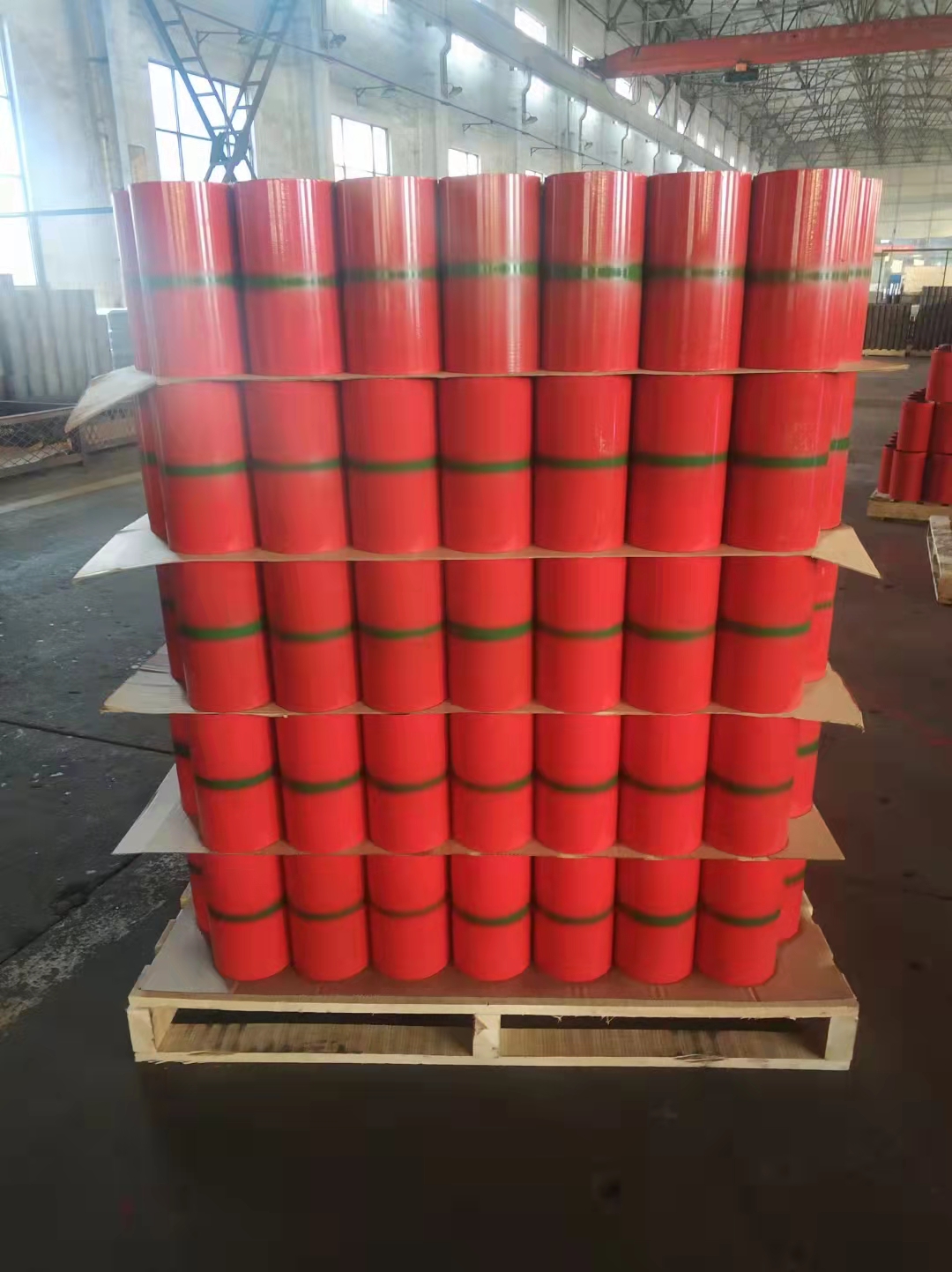 Red-coated API couplings with a single green identification band, banded on pallets before shipment — coupling class is set here, not at the rig.
The Drift Band Boundary: 2⅞ and 3½ Do Not Drift Alike
7.10 requires a full-length drift test
API Specification 5CT, 11th Edition, clause 7.10 states that "Each length of pipe shall be drift-tested throughout its entire length", and that "Drift dimensions (length and diameter) shall conform to Table C.23 or Table E.23." Drift on standard tubing is a specification requirement with a fixed mandrel, not a purchase-order variable and not something imported from API 5B. The clause also fixes when the test happens: drift testing "may be done plain end or in threaded condition", and the post-make-up re-drift below is conditional on the pipe having been drifted full-length before the couplings went on. The one purchase-order route into drift is alternative drift, which Table 5 — Optional Requirements Specified by the Purchaser (Tubing) lists against 7.10, and pipe furnished that way must be marked accordingly under Section 10.
2⅞ is the last size in the smaller-deduction band
Table C.23 gives the tubing drift as a deduction from the inside diameter d: d − 2.38 mm (3/32 in.) for Label 1 up to and including 2⅞, d − 3.18 mm (1/8 in.) above 2⅞ through 8⅝, and d − 3.97 mm above 8⅝ to below 10¾.
The flat "one-eighth inch less than ID" rule is wrong at exactly this size. 2⅞ sits on the last row of the 3/32 in. band and 3½ sits on the first row of the 1/8 in. band, so a single rule cannot be right for both. Apply 1/8 in. to a 6.4 lb/ft 2⅞ joint and you get 62.00 − 3.18 = 58.82 mm (2.316 in.). The API drift is 62.00 − 2.38 = 59.62 mm (2.347 in.). The rule understates the available bore by 0.80 mm (0.031 in.) — which is the wrong direction to be wrong in when a tool OD is being chosen, because it makes you reject clearance you actually have, and it destroys any confidence in the same rule at 3½, where it happens to be right.
The tubing mandrel is a harder test than the casing mandrel
The deduction is only half of Table C.23; mandrel length is the other half, and it is where tubing and casing part company. The standard tubing mandrel is 1067 mm (42 in.) long, against 152 mm or 305 mm for casing. A rigid cylinder seven times longer cannot negotiate a bore that a short one passes without noticing, so straightness deviation, local ovality or an internal upset transition that is invisible on a casing drift shows up on a tubing drift. In our own order book, drift rejects sit disproportionately on tubing rather than casing, and our reading of that is the mandrel, not the mill — a 1067 mm gauge simply finds geometry a 152 mm gauge never touches.
The second half of 7.10 surprises people, and it is conditional. Where the pipe has been drift-tested full-length before coupling installation, it must then be re-drifted a minimum of 1.1 m (42 in.) from the coupled end after power-tight make-up, covering any area the make-up equipment could have affected. Make-up can pull the pin bore below drift, so passing as plain-end pipe does not carry over to the finished joint. Name that re-drift in any third-party inspection scope.
Alternative drift at 2⅞ is a purchase-agreement item, not a table lookup
Alternative drift is available on tubing — Table 5 lists "Alternative drift requirements — 7.10" as an explicit purchaser election for tubing — but there is no mandrel to read off. Table C.24, which tabulates alternative drift mandrel sizes, is populated for casing sizes and carries no tubing rows, and 7.10 b) covers exactly that case: "pipe in sizes and masses not in Table C.24 or Table E.24 shall be tested with the alternative drift mandrels as specified in the purchase agreement." So at 2⅞ the purchase agreement itself has to state the mandrel diameter and length, the mill drifts to that, and the pipe is marked as alternative-drift pipe under Section 10. What you cannot do is write "alternative drift per Table C.24" and expect a defined test — that line specifies nothing at this size. The other routes out of a tight drift remain a lighter mass, a different tool string, or a premium connection with a different bore geometry.
The Market-Common Weight Band
Six masses exist at 2⅞; the market runs three. 6.4/6.5, 7.8/7.9 and 8.6/8.7 lb/ft are the commercial band, with 6.4/6.5 the workhorse and 8.6/8.7 the usual step up when burst or collapse demands it. The 9.35, 10.5 and 11.5 lb/ft masses are catalogued but rarely ordered as production tubing, and in L80 the end-finish column explains part of why: 10.5 and 11.5 lb/ft are plain-end only, and 9.35 lb/ft is plain-end or external-upset only (Table C.2, L80/R95 column, reading P, P and PU). None of the three can be ordered as a non-upset threaded-and-coupled joint in this grade. Beyond that, by the time a design needs an 11.18 mm wall in a 73.02 mm OD it has usually moved to a different size or a higher grade rather than a 1.994 in. bore.
The dual designation is the thing to understand before comparing a PO with a certificate. The same wall carries two mass numbers — 6.4 lb/ft non-upset and 6.5 lb/ft external-upset — because the designation includes the end finish. Both are 5.51 mm wall, 62.00 mm ID and 9.17 kg/m plain-end mass; the 0.1 lb/ft difference is the upset metal, not a different pipe. A PO that says 6.4 and a mill certificate that says 6.5 are not necessarily in conflict — check the end finish column before raising it. They are in conflict if the PO said NU and the certificate says EU.
The mass-versus-burst-versus-flow-area trade-off across the whole tubing range is worked through in the API 5CT tubing sizes and selection guide →. To match a size and grade to well conditions, use the pipe grade selector →.
The Grade Is Already Decided
L80 is on a 2⅞″ string because the service is sour, and its envelope is fixed: 552 MPa (80 ksi) minimum yield, 655 MPa (95 ksi) maximum yield, 655 MPa (95 ksi) minimum tensile, and a maximum mean hardness of 23.0 HRC / 241 HBW (API 5CT Table C.5), quenched and tempered. The minimum tempering temperature is type-dependent in Table C.3: 566 °C (1050 °F) for L80 Type 1 and L80 3Cr, and 593 °C (1100 °F) for L80 9Cr and L80 13Cr. What bites harder on tubing than on casing is the type: clause 1.3 makes bare "L80" applicable to L80 Type 1, L80 3Cr, L80 9Cr and L80 13Cr, and on tubing the choice changes more than the chemistry — 13Cr shifts the mass correction the mill applies, changes the thread compound and running practice, and changes the storage and protection regime for a string that may sit in a yard through a monsoon. L80 hardness testing frequency is set by clause 9.6.3 at the same frequency as tensile testing, and Table C.32 puts tensile testing for L80 Type 1 and L80 3Cr at Label 1 ≤ 4½ at two tests per lot — not per length. Table C.35 is the hardness-frequency table that 9.6 points to; per-length hardness testing is clause 9.6.4 and applies to C90, T95 and C110. Full grade detail: API 5CT L80 casing and tubing →, the hardness acceptance criteria in the L80 hardness trap →, and the API 5CT specification tables →.
When NOT to Run 2⅞″ L80
- High-rate gas wells where erosional velocity governs. A 62.00 mm bore is a 3,019 mm² flow area, and you cannot buy flow area back inside a fixed 73.02 mm OD. Above the rate where velocity approaches the erosional limit the answer is 3½″ or larger, not a lighter 2⅞″ wall.
- Deep strings where connection tension governs before pipe-body tension does. The 6.4 lb/ft non-upset pin is cut into a 5.51 mm wall with no added metal. Where hang weight approaches the connection's capacity rather than the 645 kN pipe-body yield, the answer is EU or a premium connection, not more grade.
- CO₂-dominated wells. L80 Type 1 is carbon-manganese with no minimum chromium; where CO₂ partial pressure drives the corrosion allowance the specification is L80-13Cr or a higher CRA →.
- Gas-tight service on API round thread. API 8-round and 10-round seal on thread compound trapped in the thread helix; there is no metal-to-metal seal surface in the connection, which is the barrier a gas-tight rating is normally built on. If the completion must hold gas across the connection, that decision is premium regardless of mass and grade.
- A 4½″ annulus already proven marginal. If the clearance table above puts you inside the coupling tolerance band, the honest answer is a smaller string or a flush premium connection — not a regular coupling with a note in the running procedure.
Purchase Order: The Complete 2⅞″ L80 Spec
Seven lines. The first four are where the errors are.
- Size and mass: "2⅞″, 6.5 lb/ft" — the mass is mandatory, it sets wall, ID, drift and every pressure rating.
- End finish: "EUE" or "NU" — written as the end finish, never as "8RD", which does not distinguish 8 TPI external-upset from 10 TPI non-upset at this size.
- Coupling class: "regular" or "special clearance" — a separate line from the end finish, and Table 4 treats it that way, listing regular couplings with special bevel and special clearance couplings as their own purchaser-supplied items. Silence selects regular, and the mill is compliant in shipping 93.17 mm couplings against an order that needed 87.88 mm.
- Grade with type: "L80 Type 1" or "L80 13Cr" — bare "L80" spans four types under clause 1.3 and does not identify a product.
- Drift: "standard drift per API 5CT 7.10 and Table C.23; alternative drift not applied" — one line that closes the flat-rule assumption and puts the 1.1 m post-make-up re-drift inside the inspection scope.
- Range and process: Range 2 unless the completion requires otherwise; seamless or electric-welded, stated, since Table 4 — Purchaser-supplied Information (Tubing) lists it as information the manufacturer must obtain from the purchaser.
- Protection and documentation: thread protectors fitted both ends, storage compound specified, EN 10204 3.1 mill certificate as the minimum and 3.2 where the project or market requires it.
Three checks on receipt catch most of what goes wrong here. Caliper the coupling OD against the class ordered — 88.90, 93.17 or 87.88 mm, at ±1 % regular and ±0.38 mm special clearance. Confirm the end finish on the certificate matches the mass designation, so a 6.5 lb/ft entry does not sit beside an NU description. And confirm the drift statement cites Table C.23, not a nominal ID minus one eighth of an inch.
Frequently Asked Questions
What is the drift diameter of 2 7/8 tubing?
It depends on the mass, and it is not the inside diameter minus one eighth of an inch. API 5CT Table C.23 sets the tubing drift as the inside diameter d minus 2.38 mm (3/32 in.) for Label 1 sizes up to and including 2 7/8, so a 6.4 lb/ft joint with a 62.00 mm (2.441 in.) ID drifts 59.62 mm (2.347 in.). The 7.8 lb/ft drifts 56.62 mm (2.229 in.), the 8.6 lb/ft drifts 55.00 mm (2.165 in.) and the 9.35 lb/ft drifts 53.36 mm (2.101 in.). Apply the flat one-eighth-inch rule at this size and you will plan against 2.316 in., which is 0.031 in. undersize.
What is the coupling OD on 2 7/8 EUE tubing?
There are three answers at this size and a purchase order has to pick one. A non-upset (NU) regular coupling is 88.90 mm (3.500 in.) per API 5CT Table C.29. An external-upset (EU) regular coupling is 93.17 mm (3.668 in.) per Table C.30, and an EU special clearance coupling is 87.88 mm (3.460 in.) from the same table. Writing 2 7/8 EUE on its own selects the 93.17 mm coupling by default, because regular is what a mill runs unless special clearance is called out separately.
Will 2 7/8 EUE tubing run inside 7 inch casing?
Yes, with a large margin. A 7 in. 26 lb/ft casing string has an API drift of 156.24 mm (6.151 in.), and an EU regular coupling at 93.17 mm leaves 31.5 mm (1.24 in.) of radial clearance. The clearance question only becomes real inside 5 1/2 in. and 4 1/2 in. production casing, and it becomes decisive in heavy-wall 4 1/2 in., where a 13.5 lb/ft string drifts 96.38 mm and an EU regular coupling leaves only 1.6 mm per side before tolerances are applied.
Does API 5CT require a drift test on tubing, or is drift a purchase-order item?
API 5CT requires it. Clause 7.10 states that each length of pipe shall be drift-tested throughout its entire length, and that drift dimensions shall conform to Table C.23 or Table E.23. Drift on standard tubing is therefore a specification requirement with a fixed mandrel size, not something the purchase order supplies. The one place the purchase order legitimately enters is alternative drift, which Table 5 lists as an optional requirement the purchaser may specify under 7.10; because Table C.24 tabulates alternative mandrels for casing sizes only, on 2 7/8 tubing the mandrel dimension must be written into the purchase agreement under 7.10 b), and the pipe is then marked accordingly under Section 10.
Do 2 7/8 and 3 1/2 tubing use the same drift deduction?
No, and this is the most commonly repeated error at these two sizes. API 5CT Table C.23 deducts 2.38 mm (3/32 in.) from the inside diameter for Label 1 sizes up to and including 2 7/8, and 3.18 mm (1/8 in.) for sizes above 2 7/8 through 8 5/8. 2 7/8 is the last size in the smaller-deduction band and 3 1/2 is the first size in the larger one, so a single flat rule applied across both sizes will be wrong on one of them.
When should I order special clearance couplings on 2 7/8 tubing?
When the annular gap between the coupling and the casing drift is too small for the running conditions, most often inside 4 1/2 in. or heavy-wall 5 1/2 in. production casing, or where control lines, capillary strings or a gas-lift mandrel share the annulus. Special clearance is a separate purchase-order line from the NU or EU end finish, and it is not available at every size — API 5CT lists a special clearance coupling diameter at 2 3/8, 2 7/8 and 3 1/2 tubing, but the column is blank at 4 and 4 1/2.
What weight of 2 7/8 L80 tubing should I order?
The commercial band is 6.4 to 8.6 lb/ft non-upset (6.5 to 8.7 lb/ft external-upset), and 6.4/6.5 lb/ft is the workhorse — 5.51 mm wall, 62.00 mm ID, 59.62 mm drift. Order heavier only when the burst, collapse or tensile design demands it, because every step up costs inside diameter: 8.6 lb/ft drops the drift to 55.00 mm (2.165 in.), which can exclude tools that pass the lighter wall. The full weight ladder and the burst-against-flow-area trade-off are set out in the API 5CT tubing sizes and selection guide.
Why does my 2 7/8 tubing get re-drifted after the couplings go on?
Because API 5CT 7.10 requires it where the pipe was drift-tested full-length before the couplings went on. Drift testing may be done plain-end or in the threaded condition, and 7.10 says that if the pipe has been drift-tested full-length before coupling installation, it shall also be drift-tested a minimum of 1.1 m (42 in.) from the coupled end after power-tight make-up, since the make-up itself can pull the bore of the pin end below drift. A joint that passed the full-length drift as plain-end pipe is therefore not automatically a joint that passes after threading and coupling, and this is one of the checks worth naming explicitly for a third-party inspector at the mill.