Tubing connections are specified differently from casing connections. While casing uses BTC as its primary API connection, production tubing predominantly uses the EU (External Upset) 8-round thread connection — commonly called EUE — as the standard API specification. Understanding the difference between EU and NU tubing, their tensile ratings, coupling dimensions, and when premium connections are required is essential for correct tubing string design.
ZC Steel Pipe supplies API 5CT tubing in EU and NU connections across all grades from J55 through C110, including L80 13Cr and T95 for sour and corrosive service, with premium connections available for all grades. Most of our West Africa and Middle East orders for production tubing specify EUE as the default — NUE appears primarily on short, shallow strings or recompletion strings where the running clearance has already been engineered to be tight. This guide covers EU and NU tubing connection specifications, dimensional data, tensile ratings, worked calculations, named failure modes, and when to step up to premium connections.
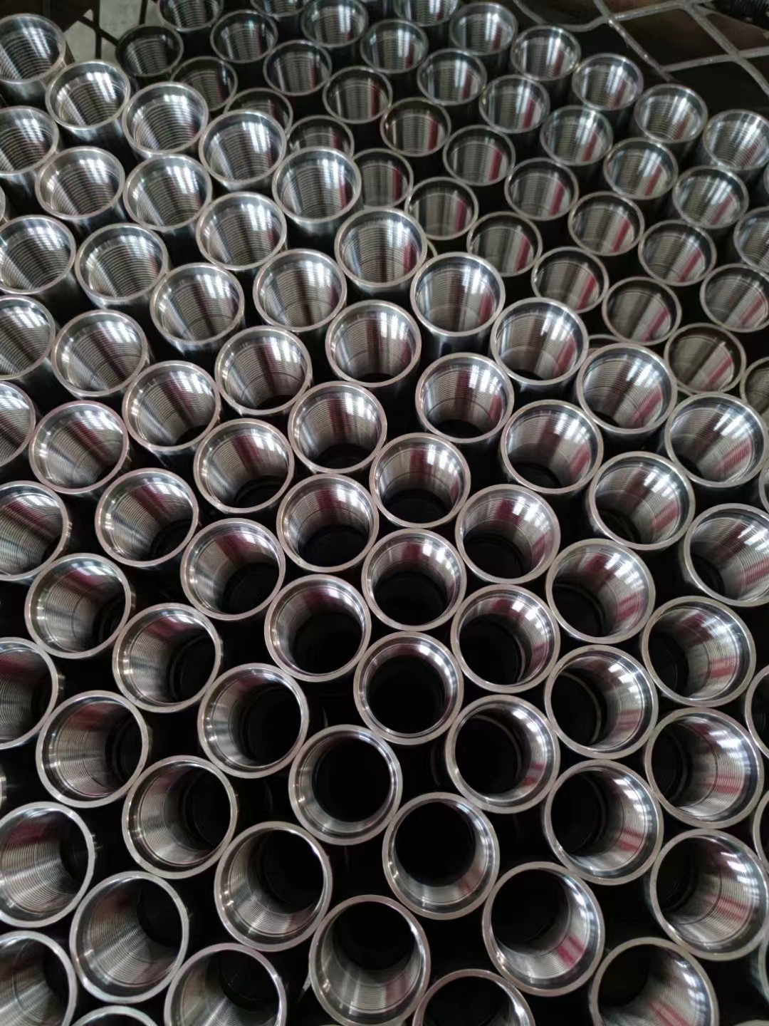 Machined API 5CT couplings viewed end-on — ZC supplies EU and NU tubing couplings across all grades from J55 through C110.
Quick Answer
For the majority of production tubing, EUE (external upset, 8-round) is the default, because the upset thickens the pipe end so the thread is not cut into the pipe wall. The clearance penalty is smaller than the folklore suggests: at 2⅞″ the EU regular coupling is 93.17 mm against 88.90 mm for NU — 4.27 mm of diameter, 2.14 mm on radius (API 5CT Tables C.30 and C.29). And where the annulus is genuinely tight, the answer is usually not NU at all: an EU special clearance coupling at 2⅞″ is 87.88 mm, 1.02 mm smaller than the NU coupling, and it keeps the upset. That trade is worked in full in the 2⅞″ L80 tubing weight, coupling and drift page →. For gas-tight service, deviated or horizontal wells, or 13Cr and CRA grades, step past both API round-thread connections to a premium metal-to-metal seal — see BTC vs premium connection selection for that decision.
What we see on completion engineering reviews: the most common EUE design error we meet is a clearance sum done against the wrong coupling table. A team sizes 3-1/2 inch EUE tubing for 5-1/2 inch 23 lb/ft casing and writes down a 107.95 mm coupling OD — but 107.95 mm is the non-upset coupling from API 5CT Table C.29. The external upset coupling at 3-1/2 is 114.30 mm (Table C.30). Against that casing's 115.44 mm drift the real radial gap is 0.57 mm, not the several millimetres the sum showed, and 0.57 mm is inside the ±1 % tolerance the standard puts on the coupling diameter. We ask which table a coupling OD came from before we quote a tight annulus, because the two tables sit on facing pages and the non-upset one is first.
1. EU and NU Tubing — The Key Difference
The fundamental difference between EU and NU tubing is whether the pipe ends are upset:
External Upset (EU): The pipe ends are hot-upset during manufacturing to increase the OD at both ends. This enlarged end diameter allows a longer threaded coupling with more thread engagement, providing higher tensile capacity. The coupling OD is larger than the pipe body OD.
Non-Upset (NU): No upsetting is applied. The pipe end OD equals the pipe body OD. Thread engagement is shorter, tensile capacity is lower, but there is no OD enlargement at the coupling location.
| Property | EU (EUE) | NU (NUE) |
|---|---|---|
| End OD | Larger than pipe body | Same as pipe body |
| Coupling OD at 2⅞″ | 93.17 mm regular; 87.88 mm special clearance | 88.90 mm |
| Coupling minimum length NL at 2⅞″ | 133.35 mm | 130.18 mm |
| Critical section at the connection | Thickened upset metal at the pin | The pipe wall itself, at the thread root |
| Drift clearance | Coupling must be checked against casing drift | Coupling must be checked against casing drift |
| Common application | Standard production tubing | Tight clearance applications |
| Thread form | 8-round, 8 TPI | 8-round, 8 TPI |
Where the load path runs is the reason EUE dominates production tubing. On a non-upset joint the thread is machined into the pipe wall, so the wall thickness the string hangs on is the wall minus the thread depth; on an external upset joint the pipe end is thickened first, and the thread is cut into that added metal rather than into the body. That is a structural difference, not a percentage — API 5CT is a product specification and does not publish connection efficiency ratings, and any efficiency figure quoted to you should be traced back to the document and edition it came from before it goes into a string design. Note also that the two coupling ODs in the table are much closer than the "EU is bulky, NU is slim" framing implies, and that an EU special clearance coupling undercuts the NU coupling outright at 2⅜″, 2⅞″ and 3½″.
2. EUE Tubing — Specifications and Dimensions
EUE (External Upset End) with 8-round thread is the standard production tubing connection globally. It is specified in API Specification 5CT, 11th Edition, and the thread form is defined in API 5B.
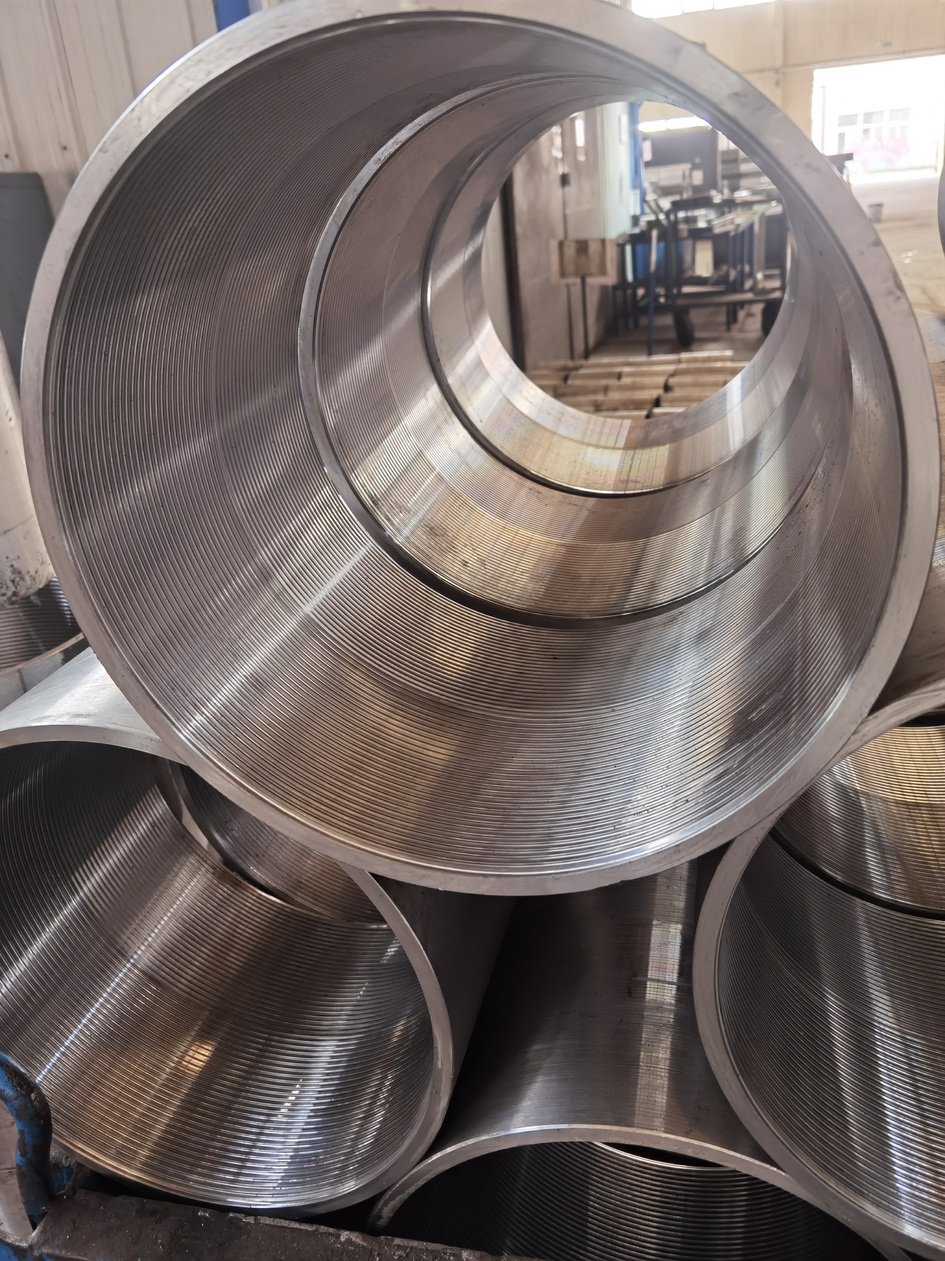 Internal thread detail on stacked couplings — the 8-round thread form defined in API 5B is used for both EUE and NUE tubing.
Common EUE tubing sizes:
| OD (in) | OD (mm) | Weight (lb/ft) | Wall (mm) | ID (mm) | Coupling OD (mm) | Drift (mm) |
|---|---|---|---|---|---|---|
| 1.900 | 48.26 | 2.90 | 3.68 | 40.90 | 63.50 | 38.52 |
| 1.900 | 48.26 | 3.73 | 5.08 | 38.10 | 63.50 | 35.72 |
| 2-3/8 | 60.32 | 4.70 | 4.83 | 50.66 | 77.80 | 48.28 |
| 2-3/8 | 60.32 | 5.95 | 6.45 | 47.42 | 77.80 | 45.04 |
| 2-3/8 | 60.32 | 7.45 | 8.53 | 43.26 | 77.80 | 40.88 |
| 2-7/8 | 73.02 | 6.50 | 5.51 | 62.00 | 93.17 | 59.62 |
| 2-7/8 | 73.02 | 7.90 | 7.01 | 59.00 | 93.17 | 56.62 |
| 2-7/8 | 73.02 | 8.70 | 7.82 | 57.38 | 93.17 | 55.00 |
| 2-7/8 | 73.02 | 9.45 | 8.64 | 55.74 | 93.17 | 53.36 |
| 3-1/2 | 88.90 | 9.30 | 6.45 | 76.00 | 114.30 | 72.82 |
| 3-1/2 | 88.90 | 12.95 | 9.52 | 69.86 | 114.30 | 66.68 |
| 4 | 101.60 | 11.00 | 6.65 | 88.30 | 127.00 | 85.12 |
| 4-1/2 | 114.30 | 12.75 | 6.88 | 100.54 | 141.30 | 97.36 |
Every row above is an external-upset mass that Table C.2 actually lists. That matters, because most sizes carry fewer EU masses than NU masses — at 3-1/2 inch only 9.30 and 12.95 lb/ft exist as external upset, and at 4-1/2 inch only 12.75 lb/ft does. Asking a mill for "3-1/2 inch 10.20 lb/ft EUE" is asking for a combination the standard does not list.
The coupling OD column is the dimension engineering teams most often undercheck, and the check has to be made against the casing drift, not the casing ID. The 4-inch EUE coupling at 127.00 mm does not pass the 121.08 mm drift of 5-1/2 inch 17 lb/ft casing — it is 5.92 mm larger in diameter than the hole it has to go through. The 3-1/2 inch EUE coupling at 114.30 mm clears that same drift by 3.39 mm on radius, and clears 5-1/2 inch 23 lb/ft (drift 115.44 mm) by 0.57 mm — a gap narrower than the +/-1 % tolerance Table C.30 allows on the coupling itself. Run the explicit clearance calculation before finalizing any size combination.
For the complete grade and connection-class specification tables, see the API 5CT specification tables →
To match a connection type to your well conditions, use the Pipe Grade Selector →
What EU volume actually looks like: EU is the default on our tubing order book. One South American order alone was 15,000 J55 and N80Q couplings in EU and LTC across 3½″, 4½″, and 5½″ — the EU (external upset) couplings for the tubing strings and LTC for the larger-diameter casing. The coupling OD that the upset creates is exactly the dimension buyers most often skip checking against packer and casing drift; we ask for the completion clearance before confirming EU on a tight annulus.
3. NUE Tubing — Specifications and Dimensions
NUE tubing is less common but specified for tight clearance applications. The coupling OD is only slightly larger than the pipe body OD.
Common NUE tubing sizes:
| OD (in) | OD (mm) | Weight (lb/ft) | Wall (mm) | ID (mm) | Coupling OD (mm) | Drift (mm) |
|---|---|---|---|---|---|---|
| 1.050 | 26.67 | 1.14 | 2.87 | 20.93 | 33.35 | 18.55 |
| 1.315 | 33.40 | 1.70 | 3.38 | 26.64 | 42.16 | 24.26 |
| 1.660 | 42.16 | 2.09 | 3.18 | 35.80 | 52.17 | 33.42 |
| 1.900 | 48.26 | 2.40 | 3.18 | 41.90 | 55.88 | 39.52 |
| 2-3/8 | 60.32 | 4.00 | 4.24 | 51.84 | 73.02 | 49.46 |
| 2-7/8 | 73.02 | 6.40 | 5.51 | 62.00 | 88.90 | 59.62 |
| 3-1/2 | 88.90 | 7.70 | 5.49 | 77.92 | 107.95 | 74.74 |
Comparing the 2-7/8 inch row: the non-upset coupling is 88.90 mm against 93.17 mm for a regular external-upset coupling — a difference of 4.27 mm on diameter, 2.14 mm on radius. That is a smaller saving than the choice is usually credited with.
And it is not the slimmest option. Table C.30 lists a special clearance external-upset coupling at 2-7/8 inch of 87.88 mm — 1.02 mm narrower than the standard non-upset coupling. So "run non-upset when the annulus is tight" is a false economy at this size: an external-upset joint is available at less outside diameter than a plain non-upset one, and it keeps the upset. The price is bearing face and coupling mass, not bore — the pipe ID and drift are identical either way. Special clearance is listed at 2-3/8, 2-7/8 and 3-1/2 only; the column is blank at 4 and 4-1/2. The full trade-off is worked through in the 2-7/8 inch L80 tubing guide →.
For the 1.050 and 1.315 inch sizes, NUE is the only available API connection — these small-bore sizes do not have a standard EUE design.
4. Tensile Rating Comparison
Connection tensile rating is a critical design parameter for tubing string design, particularly in deep wells and gas lift completions where the string weight is significant. The joint-strength formulas that produce these ratings are set out in API 5C3.
Where the two connections differ is where the load path runs, and that is a geometry argument rather than a percentage.
On an external-upset joint the pipe end is hot-upset before threading, so the thread is cut into added metal. The section carrying the string weight at the connection is thicker than the pipe wall, which is why EU is the default wherever hang weight matters.
On a non-upset joint the thread is machined directly into the pipe wall. The critical section is the wall minus the thread depth, so the connection is necessarily weaker than the pipe body it is cut from, and the deficit grows as the wall gets thinner.
We publish no joint-strength figure here, and you should treat any you are quoted with suspicion until it is traced to a document and an edition. The joint-strength formulas belong to API 5C3; the efficiency percentages that circulate on supplier datasheets are usually undated, frequently inconsistent with each other, and rarely say which formula, grade or safety factor produced them. Compute the number for your own size, grade and wall, then apply your own factor.
5. Clearance Calculations — EUE Coupling vs Casing Drift
Worked Clearance Calculation — EUE Coupling OD Check
The EUE coupling OD must clear the casing drift diameter. This is not a step to delegate to the completion report — it should be done on the initial well design and again before the string is ordered.
What the standard fixes, and what it leaves to you. API 5CT sets the coupling outside diameter (Table C.30 for external upset, Table C.29 for non-upset) and the casing drift (7.10 and Table C.23). It does not set a minimum annular clearance — that is your call, against your own running conditions. What it does give you is the tolerance to design against: Table C.30 allows ±1 % on the regular coupling OD, which is ±0.93 mm at 2-7/8 inch and ±1.14 mm at 3-1/2 inch, and a tighter ±0.38 mm on the special-clearance diameter. A gap narrower than the tolerance stack is not a gap.
Check the coupling against the casing DRIFT, not the casing ID. The drift is the guaranteed minimum bore; the ID is nominal.
3-1/2 inch EUE (coupling OD 114.30 mm, Table C.30) in 5-1/2 inch casing:
| Casing | Drift (mm) | Radial clearance | Decision |
|---|---|---|---|
| 5-1/2 inch 17.00 lb/ft | 121.08 | (121.08 − 114.30) / 2 = 3.39 mm | Workable — still check the tolerance stack |
| 5-1/2 inch 20.00 lb/ft | 118.18 | (118.18 − 114.30) / 2 = 1.94 mm | Marginal — inside twice the coupling tolerance |
| 5-1/2 inch 23.00 lb/ft | 115.44 | (115.44 − 114.30) / 2 = 0.57 mm | Not a clearance — narrower than the ±1 % tolerance alone |
| 5-1/2 inch 26.80 lb/ft | 111.12 | (111.12 − 114.30) / 2 = −1.59 mm | Will not enter the hole |
The last row is the one worth pausing on. In 5-1/2 inch 26.80 lb/ft casing a 3-1/2 inch EUE coupling is larger in diameter than the drift it has to pass — this is not a marginal clearance to be reviewed, it is a string that cannot be run. Note also that API 5CT lists no 5-1/2 inch 26 lb/ft casing; the row is 26.80 lb/ft, and a clearance sum done against a weight that does not exist is a sum done against an invented drift.
Dropping to 2-7/8 inch EUE clears it comfortably: coupling 93.17 mm against the same 111.12 mm drift is (111.12 − 93.17) / 2 = 8.98 mm on radius. The other route is a special-clearance external-upset coupling where one is listed — at 3-1/2 inch that is 106.17 mm, which turns the −1.59 mm interference into (111.12 − 106.17) / 2 = 2.48 mm of radial clearance and keeps the 3-1/2 inch bore. That is precisely the case special clearance exists for.
Tensile Check — 2-7/8 inch N80 EUE at 3,000m
For a 2-7/8 inch N80 EUE tubing string in a 3,000m well, start from the load, then compare it against a connection rating you have computed for that exact size, grade and wall:
String weight = 3,000m × 6.40 lb/ft × 0.45359 kg/lb × 9.81 m/s² / 1,000 = approximately 84.9 kN
For scale, the pipe-body yield of that joint is 552 MPa acting on a 1,168.6 mm² cross-section, or about 645 kN — so the hanging weight is roughly an eighth of what the pipe body alone will carry, before any connection derating. That margin is why axial tension is rarely the governing case on a 3,000 m 2-7/8 inch string, and why the checks that do bite are clearance, drift and bending. Compute the connection rating itself from API 5C3 rather than from a datasheet percentage. For burst and collapse checks on the same string, use the Barlow pressure calculator → — enter the pipe OD, wall thickness, and grade yield strength to verify the pressure ratings against your wellhead and reservoir conditions.
A connection tensile rating, however it was computed, is a room-temperature, axial-load number. API 5CT does not publish one — it specifies the pipe, not the joint capacity. Such a rating does not account for the combined tension-bending loads in deviated wells, nor for the reduction in thread compound friction that occurs when the compound partially washes out during long production periods. In deviated completions, the bending stress at the connection adds to the axial tension — the combined load can exceed the connection rating at wellbore inclinations that appear moderate (40–50°). For tubing strings where bending is significant, the EUE connection rating must be checked against the triaxial stress state, not just the axial tension.
6. Named EUE and NUE Failure Modes
Failure Mode 1: EUE Gas Leak — Compound Washout Under Cyclic Pressure
Mechanism: EUE 8-round thread depends on thread compound to seal the helical thread gap. In gas wells, the high-pressure gas phase applies differential pressure across the thread flanks. Over repeated pressure cycles — start-up, shut-in, drawdown — thread compound slowly migrates out of the thread form, particularly at the last-engaged-thread (LET) where stress concentration is highest. Once the compound film is locally depleted, gas migrates through the thread helix as a leak path. The leak rate starts small and grows with each pressure cycle.
Diagnostic: Sustained casing pressure (SCP) increasing over time, detected at A-annulus. Gas detected between tubing and casing at wellhead. EUE connection shows compound residue in the annular space around the coupling. Pressure test of the pulled connection fails gas integrity test.
Fix: EUE is not rated for gas-tight service. The correct specification is a premium metal-to-metal seal connection — ISO 13679 CAL III minimum for gas wells. Do not attempt to re-seal EUE gas leaks with additional compound. If EUE is deployed in a gas well and sustained casing pressure develops, plan a workover to replace the connection rather than waiting for the leak rate to stabilize.
Failure Mode 2: NUE Tensile Pull-Out in Deep Wells
Mechanism: on a non-upset joint the thread is cut into the pipe wall, so the connection is necessarily weaker than the pipe body — the critical section is the wall minus the thread depth. In deep wells, the cumulative string weight approaches or exceeds that reduced section's capacity, particularly for the top joint which carries the full string weight. At the NUE rating limit, the thread form deforms plastically (jump-out), releasing the string suddenly — this is a wellbore incident, not a gradual failure.
Diagnostic: Loss of string weight at surface (sudden reduction in hook load). String is stuck or lost in the well. Top joint shows thread deformation consistent with tensile overload.
Fix: For wells deeper than 2,000m, specify EUE not NUE. Run a tensile check: string weight (length × weight per meter × gravity) must be less than 80% of the connection tensile rating to maintain a 1.25 safety factor. For deviated wells, add the bending component to the tensile load before checking against the rating.
Failure Mode 3: EUE Coupling OD String Stuck on Completion Equipment
Mechanism: an external-upset coupling stands well proud of the pipe body — from Table C.30 against the pipe OD, 17.5 mm at 2-3/8 inch, 20.2 mm at 2-7/8, 25.4 mm at 3-1/2 and 4, and 27.0 mm at 4-1/2. If the coupling OD is not checked against all downhole equipment — packers, safety valves, gas lift mandrels, nipple profiles — the coupling can contact and lodge against an eccentric or undersized bore. This occurs particularly when the well has been re-completed with equipment from different vendors, where the actual bore may differ from the nominal published dimension.
Diagnostic: Overpull required to set or retrieve tubing. Weight indicator shows sustained increased drag consistent with a stuck coupling. Camera survey or impression block confirms the coupling location as the obstruction.
Fix: Before specifying EUE, create a coupling clearance register: for each piece of downhole equipment in the completion, record the minimum bore and confirm it exceeds the EUE coupling OD by the operator's minimum radial clearance. Use premium connections with flush or near-flush OD where equipment clearance is tight.
7. When NOT to Use EUE Tubing Connections
EUE is the right connection for the majority of production tubing strings — sweet oil wells, moderate-depth gas lift strings, and sour service wells where the fluid and depth profile fall within the EUE load envelope. The following conditions take the application outside that envelope.
| Condition | Why EUE Is Unsuitable | Correct Connection |
|---|---|---|
| Gas producer | Not gas-tight; thread compound is the only seal | Premium metal-to-metal seal, ISO 13679 CAL III or IV |
| Well deeper than 3,000m | NUE tensile rating may be exceeded — check EUE | EUE after tensile verification |
| Deviated well > 30° inclination | Bending adds to tension; EUE triaxial rating needed | EUE with combined load check or premium |
| HPHT well | Combined loads exceed EUE capability | Premium connection ISO 13679 CAL IV |
| L80-13Cr or CRA grade | Connection must match pipe body corrosion resistance | Premium connection with same alloy coupling |
| Tight OD clearance | Coupling OD may contact completion equipment | Premium near-flush connection |
The gas producer case is the most frequently misapplied. EUE appears on L80 13Cr purchase orders for gas condensate wells at an industry-wide frequency that is higher than it should be. The 13Cr pipe body provides CO2 corrosion resistance — but the EUE 8-round thread, sealed only with compound, will leak gas on a sufficient number of pressure cycles. Matching a premium metal-to-metal seal connection to an L80 13Cr pipe body is not over-engineering; it is the only specification that achieves both corrosion resistance and gas-tight integrity.
8. Grade Selection for EU Tubing
| Grade | EU Availability | Application |
|---|---|---|
| J55 | EUE and NUE | Shallow, low pressure, sweet service |
| N80-1 | EUE and NUE | Medium depth, sweet service |
| L80-1 | EUE | Sour service, mild to moderate H₂S |
| L80 13Cr | EUE | CO₂ corrosive gas condensate wells |
| T95 | EUE | Moderate sour service, deeper wells |
| P110 | EUE | Deep sweet HPHT wells |
| C110 | EUE | Severe sour service |
| Q125 | Premium preferred | Ultra-deep — premium connection standard |
For mild-to-moderate H₂S service, L80-1 EUE is the standard sour-service tubing specification — see the L80 sour-service grade specifications for the hardness requirements and the supplementary requirements worth naming on a purchase order. For L80 13Cr and higher CRA grades, EUE is available but premium connections are typically required for gas wells due to the gas-tight seal requirement. Q125 in EUE is rarely available from mills in standard stock — if a project specifies Q125 EUE, expect extended lead times and verify mill capability before committing the delivery schedule to the operator.
9. Purchase Order Specification — Getting It Right
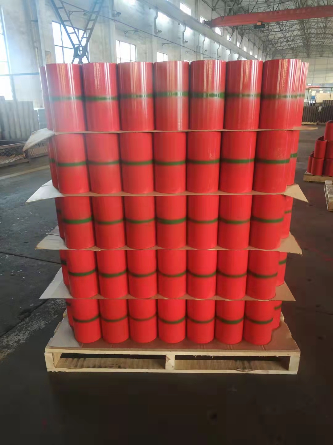 Red-coated couplings palletised and shrink-wrapped for export — the coupling material, the thread compound and the coupling class all belong on the purchase order.
When ordering EU or NU tubing, specify:
- Standard: API 5CT / ISO 11960
- Grade and type (e.g. L80 Type 1, L80 Type 13Cr)
- OD and nominal weight (lb/ft)
- End finish: EUE (external upset, 8-round thread) or NUE (non-upset, 8-round thread)
- Length range: Range 2 (8.0–9.6m) standard for tubing
- Supplementary requirements by Annex A number, if any (for example A.3 / SR 2 supplementary non-destructive examination)
- MTC: EN 10204 3.1 or 3.2
- Thread compound specification
- Drift diameter confirmation
Procurement Trap — L80 13Cr EUE on a Gas Condensate Well
Wrong PO: "2-7/8 inch 6.40 lb/ft L80 13Cr tubing, EUE, API 5CT, Range 2, 400 joints — gas condensate producer"
What the mill ships: EUE connections with carbon steel couplings. L80-13Cr pipe body with standard API EUE coupling — not necessarily 13Cr coupling material. The connection is not gas-tight. The galvanic couple between a 13Cr body and a carbon steel coupling in a CO2-bearing condensate fluid accelerates coupling corrosion, creating an integrity failure that has nothing to do with the pipe body grade selected.
Correct PO: "2-7/8 inch 6.40 lb/ft L80 Type 13Cr per API Specification 5CT, 11th Edition, premium metal-to-metal seal connection [specify connection designation], ISO 13679 CAL III minimum, 13Cr compatible coupling material, Q+T heat treatment, hardness reported on the MTC with the test frequency agreed under 9.6.1, Range 2, EN 10204 3.2 MTC, 400 joints."
The 23.0 HRC figure is API 5CT's own, from Table C.5, and it is a maximum mean hardness — 6.7.1 a) 1) sets a separate 24.0 HRC single-indentation reject. Naming it on the PO is worth doing because it pins the acceptance basis in writing. Note also what API 5CT does not give you by default: 9.6.3 puts L80 hardness testing at the tensile-test frequency, which Table C.35 sets at two tests per lot — not a reading per joint. Per-joint hardness reporting is a negotiated addition under 9.6.1, so ask for it at order stage or it will not be on the certificate.
One scoping point that is routinely missed: L80 13Cr is a CO₂ and chloride grade, not a sour-service grade. It shares L80 Type 1's hardness ceiling, which is why the two get conflated. If the well carries H₂S as well as CO₂, the material-selection question belongs to NACE MR0175 / ISO 15156, which API 5CT's own Caution in Section 1 points you to — and to that standard, not this page or the mill's datasheet.
For premium connections, replace EUE/NUE with the specific connection series designation and include the connection qualification standard (ISO 13679 CAL III or CAL IV as appropriate). On ZC orders for West African operators, we include the connection qualification test report number on the MTC as a line item — this prevents disputes at the port of entry where inspectors ask for the connection certification separately from the pipe body MTC.
Frequently Asked Questions
What is the difference between EU and NU tubing connections?
EU (External Upset) tubing has an enlarged OD at both pipe ends, achieved by hot upsetting during manufacture. This larger end diameter accommodates longer thread engagement and provides higher tensile capacity. NU (Non-Upset) tubing has the same OD at the ends as the pipe body — no upsetting is applied. The upset puts extra metal at the pin, so the thread is cut into thickened material instead of into the pipe wall — that is why EU is the default wherever hang weight matters. The coupling diameters differ far less than most people assume: at 2-7/8 the NU coupling is 88.90 mm and the EU regular coupling is 93.17 mm, a difference of 4.27 mm (API 5CT Tables C.29 and C.30).
What does EUE mean for tubing connections?
EUE stands for External Upset End — it refers to tubing with external upset ends that accommodate the API 8-round thread (8 TPI) connection. EUE 8-round is the most common API tubing connection globally and is the default specification for most production tubing strings in L80, N80, and J55 grades. The external upset increases the OD at the coupling location, which must be considered when calculating running clearances inside the production casing.
What is NUE tubing and when is it used?
NUE stands for Non-Upset End, referring to tubing with no OD enlargement at the ends. On NUE the thread is cut directly into the pipe wall, so the wall at the thread root is the critical section; the coupling is also shorter, 130.18 mm minimum length at 2-7/8 against 133.35 mm for EU (API 5CT Tables C.29 and C.30). NUE is specified where bore clearance inside the casing is critical or on shallow, low-load strings. NUE is less common than EUE in modern completion designs.
What thread form is used for API tubing connections?
Standard API tubing connections use the 8-round thread form — 8 threads per inch with a rounded thread profile — defined in API 5B. Both EUE and NUE use this thread form. The external upset on EUE allows longer thread engagement (longer coupling) than NUE, which provides the higher tensile capacity. Premium tubing connections use proprietary thread forms (trapezoidal, wedge, or modified buttress) that provide gas-tight metal-to-metal sealing not achievable with API round thread.
Can EUE tubing be run through a packer?
EUE tubing can be run through most standard bore packers and completion equipment designed for the nominal tubing OD. However the coupling OD of EUE tubing is larger than the pipe body OD and must be checked against the packer bore and any other completion equipment the tubing string must pass through. Always verify coupling OD clearance against the minimum bore of all downhole equipment before specifying EUE tubing for a completion with restrictive bore requirements.
What grades are available for EUE tubing?
EUE tubing is available in all API 5CT grades from J55 through P110 and C110 in standard sizes. L80 13Cr EUE is the standard specification for CO2-corrosive gas condensate wells. For sour service, L80 Type 1 EUE is the usual specification. T95 and C110 EUE are specified for deeper sour service wells. Q125 tubing is less commonly available in EUE — premium connections are generally specified for Q125 grade.
What is the coupling OD for EUE tubing?
API 5CT Table C.30 gives the external upset tubing coupling outside diameter W directly: 77.80 mm at 2-3/8, 93.17 mm at 2-7/8, 114.30 mm at 3-1/2, 127.00 mm at 4 and 141.30 mm at 4-1/2, all against pipe body ODs of 60.32, 73.02, 88.90, 101.60 and 114.30 mm respectively. The same table lists a special clearance coupling at the three smallest of those sizes only — 73.91 mm at 2-3/8, 87.88 mm at 2-7/8 and 106.17 mm at 3-1/2 — and the column is blank at 4 and 4-1/2. Regular coupling OD carries a tolerance of plus or minus 1 percent and the special clearance diameter plus or minus 0.38 mm, so both bands belong in any clearance check against casing drift or packer bore.
When should premium tubing connections be specified instead of EUE?
Premium tubing connections should be specified instead of EUE when: the well produces gas and gas-tight integrity is required; the tubing string is in a deviated or horizontal well with bending loads; the grade is T95, C110, or a CRA (13Cr, Super 13Cr, duplex) where connection performance must match the pipe body; the well is HPHT with high combined loads; or the operator specification explicitly requires premium connections for the application.