Couplings are the connecting elements that join individual casing and tubing joints into a continuous wellbore string. While the pipe body receives most of the engineering attention in casing design, couplings are equally critical — a coupling failure causes the same well integrity consequences as a pipe body failure. Understanding API 5CT coupling specifications, dimensional requirements, grade matching rules, and sour service requirements is essential for correct OCTG procurement.
ZC Steel Pipe supplies API 5CT couplings for all standard casing and tubing sizes in grades J55 through Q125, with STC, LTC, BTC, and EUE/NUE thread forms. Couplings are supplied as part of complete casing and tubing string packages. This guide covers coupling specifications, OD dimensions, grade requirements, and procurement guidance.
 A batch of ZC API 5CT couplings from a South American order, stood on end to show the internal threads — J55 and N80 stock ready for thread inspection before dispatch.
On a 3,800 m L80 Type 1 sour service string ordered for a Middle East gas well, the couplings arrived marked L80 but the coupling certificate reported a yield only marginally clear of the 552 MPa (80.0 ksi) minimum that API 5CT Table C.5 sets for L80, while the pipe body sat comfortably mid-band. The couplings were from a different heat than the pipe; both heats conformed, but the inspector queried the gap and the shipment sat for a week. Our mill re-tested the coupling heat and confirmed conformance, which closed it. The lesson: never assume coupling heat equals pipe heat. They are separate stock items with separate test records, and clause 8.1 treats them as separate products.
1. Coupling Types and Thread Forms
API 5CT defines couplings for each standard connection type:
| Connection | API 5CT coupling code | Thread Form | Primary Application |
|---|---|---|---|
| STC | SC — short round thread casing | 8-round, 8 TPI | Shallow surface casing |
| LTC | LC — long round thread casing | 8-round, 8 TPI | Intermediate casing |
| BTC | BC — buttress thread casing | Buttress, 5 TPI | Production/intermediate casing |
| EUE | EU — external upset tubing | 8-round, 8 TPI | Production tubing |
| NUE | NU — non-upset tubing | 8-round, 8 TPI | Tubing, tight clearance |
Use the middle column when you read the standard's tables — Table C.7 and the dimension tables are keyed on SC, LC, BC, EU and NU, not on STC/LTC/BTC. The collision worth knowing about is SC: on a round thread coupling it means short round, and in the phrase "SC coupling" as most vendors use it, it means special clearance. Those are different things, and API 5CT abbreviates special clearance as SCC. Each coupling code has its own OD and length dimensions in API 5CT and API 5B. For the pipe-side thread forms and their load ratings, see the casing connection types guide, the BTC buttress thread field guide, and the EUE/NUE tubing connections guide.
2. Coupling OD Dimensions
Coupling OD is always larger than pipe body OD. The coupling OD determines wellbore clearance and must be checked against centralizer bore, liner hanger bore, and any downhole equipment the string must pass through. Look up pipe body OD, wall, and drift for any size with the Size & Weight Lookup →.
Casing coupling outside diameter, regular and special clearance. Read from API 5CT Table C.28 (buttress) and cross-checked against Table C.27 (round thread), which gives the same regular W at every size — so choosing long round over buttress buys no annular clearance on its own.
| Pipe OD (in) | Pipe OD (mm) | Regular W (mm) | Regular W (in) | Special clearance Wc (mm) |
|---|---|---|---|---|
| 4-1/2 | 114.30 | 133.35 | 5.250 | 123.82 |
| 5 | 127.00 | 147.32 | 5.800 | 136.52 |
| 5-1/2 | 139.70 | 160.02 | 6.300 | 149.22 |
| 6-5/8 | 168.28 | 187.71 | 7.390 | 177.80 |
| 7 | 177.80 | 200.03 | 7.875 | 187.32 |
| 7-5/8 | 193.68 | 215.90 | 8.500 | 206.38 |
| 8-5/8 | 219.08 | 244.48 | 9.625 | 231.78 |
| 9-5/8 | 244.48 | 269.88 | 10.625 | 257.18 |
| 10-3/4 | 273.05 | 298.45 | 11.750 | 285.75 |
| 11-3/4 | 298.45 | 323.85 | 12.750 | — |
| 13-3/8 | 339.72 | 365.12 | 14.375 | — |
| 16 | 406.40 | 431.80 | 17.000 | — |
| 18-5/8 | 473.08 | 508.00 | 20.000 | — |
| 20 | 508.00 | 533.40 | 21.000 | — |
A dash in the special-clearance column means Table C.28 tabulates none at that size — the reduced-OD option runs from 4-1/2 through 10-3/4 and stops. Clause 8.6, "Special Clearance Couplings—All Grades Except Q125", also scopes reduced-OD couplings to buttress casing and EU tubing, and Table C.27 carries no special-clearance column at any size. Three consequences follow, and all three are commercially live. A long-round order forecloses the clearance remedy entirely — there is no reduced-OD round thread casing coupling to order. The option is excluded on Grade Q125, which is the title of 8.6 and is reinforced by 8.4.2, where Q125 coupling dimensions are either as specified in the purchase agreement or as shown in Tables C.27 and C.28. And on 11-3/4 and larger there is no tabulated Wc at all, so clearance on the big strings has to be found in the hole, not in the coupling. Table C.1 footnote d states the same scope from the other direction: "Buttress casing is available with regular, special clearance couplings or special clearance couplings with special bevel." On the rack, clause 10.4.4 is how you tell them apart — a special clearance coupling carries a black band around the centre in addition to the grade colours.
Tubing coupling outside diameter, non-upset and external upset. NU from API 5CT Table C.29, EU regular and special clearance from Table C.28's tubing counterpart, Table C.30.
| Pipe OD (in) | Pipe OD (mm) | NU W (mm) | NU W (in) | EU regular W (mm) | EU regular W (in) | EU special clearance Wc (mm) | EU special clearance Wc (in) |
|---|---|---|---|---|---|---|---|
| 2-3/8 | 60.32 | 73.02 | 2.875 | 77.80 | 3.063 | 73.91 | 2.910 |
| 2-7/8 | 73.02 | 88.90 | 3.500 | 93.17 | 3.668 | 87.88 | 3.460 |
| 3-1/2 | 88.90 | 107.95 | 4.250 | 114.30 | 4.500 | 106.17 | 4.180 |
| 4 | 101.60 | 120.65 | 4.750 | 127.00 | 5.000 | — | — |
| 4-1/2 | 114.30 | 132.08 | 5.200 | 141.30 | 5.563 | — | — |
The NU and EU columns get conflated, and always in the same direction: a spreadsheet carries the NU figure against an EU order and the clearance calculation comes out 4.27 mm to 9.22 mm optimistic depending on size — 6.35 mm (0.250 in) at 3-1/2 inch, enough to matter inside a 4-1/2 inch liner. EU special clearance also stops at 3-1/2; Table C.30 tabulates no Wc for 4 and 4-1/2 inch EU tubing, so those strings have no reduced-OD coupling available. Per 8.6 special clearance EU couplings carry a special bevel on both ends unless otherwise specified, and per 7.14.1 they are made up handling-tight rather than power-tight.
For the complete grade ladder with tensile, hardness, and chemistry limits, see the API 5CT specification tables →
To match a grade to your well conditions, use the Pipe Grade Selector →
Coupling Quantity Calculation — Worked Example
For a 3,000 m production casing string in 7-inch 26 lb/ft L80-1 BTC, sour service:
Step 1 — Calculate joint count: Assumed average R3 joint length = 12.19 m. This is a planning assumption, not a specification value — API 5CT Table C.22 gives Range 3 casing a total range length of 10.36 m to 14.63 m with a maximum permissible variation of 1.83 m, and sets no minimum average. Confirm the mill's actual tally before committing the count. Joints required = 3,000 m ÷ 12.19 m/joint = 246 joints
Step 2 — Add spare couplings: Spare factor = 5% (for damaged or rejected couplings during running) Spare couplings = 246 × 0.05 = 12.3 → round up to 13 spares
Step 3 — Total coupling order: Total couplings = 246 + 13 = 259 couplings
Step 4 — Verify coupling OD clearance: 7-inch BTC regular coupling OD (Table C.28) = 200.03 mm (7.875 in) 7-inch BTC special clearance coupling OD Wc (Table C.28) = 187.32 mm (7.375 in) Liner hanger bore, if applicable: confirm bore ID > 200.03 mm. If it is between 187.32 mm and 200.03 mm, the special clearance coupling is the only API option at this size — and the string design has to be rerun on the reduced critical thickness of 7.11 mm (0.280 in) from Table C.7, not on the 13.46 mm (0.530 in) of the regular coupling.
Note: Clause 7.14.1 makes power-tight make-up the default — all casing couplings and regular tubing couplings are screwed on power-tight unless the purchase agreement specifies handling-tight or separate shipment. If you want to gauge and re-dope the threads before running, that is a PO line, not a courtesy. The exceptions are already in the standard: special clearance tubing couplings are handling-tight by default under 7.14.1, and Q125 couplings with API threads are shipped separately unless power-tight is specified (7.14.2).
3. Coupling Grades and Material Requirements
The default and the permitted substitutions. Clause 8.1 b) and c) require couplings to be of the same grade and type as the pipe body and to be given the same heat treatment. Clause 8.2 is the only route out of that, and it is a closed list of named substitutions — not a general "any higher grade is acceptable" rule.
Coupling grade under API 5CT clause 8.2. Every row below happens only when it is specified in the purchase agreement.
| Pipe grade | Coupling grade permitted | Clause |
|---|---|---|
| H40 | H40, J55 or K55, as-rolled / normalised / N&T / Q&T | 8.2.1 |
| J55 | J55 or K55, as-rolled / normalised / N&T / Q&T | 8.2.2 |
| K55 | K55, as-rolled / normalised / N&T / Q&T | 8.2.3 |
| J55 EU tubing | L80 Type 1 special clearance couplings, when specified | 8.2.4 |
| J55 and K55 buttress casing | L80 Type 1, when specified | 8.2.5 |
| N80 Type 1, normalised | N80 Type 1 or N80Q | 8.2.6 |
| N80 Type 1, normalised and tempered | N&T N80 Type 1, or N80Q | 8.2.7 |
| N80 Type 1 / N80Q EU tubing | P110 special clearance couplings, when specified | 8.2.8 |
| N80 Type 1 / N80Q buttress casing | P110, when specified | 8.2.9 |
| P110 buttress casing | Q125, when specified | 8.2.10 |
| L80 (all types), R95, C90, T95, C110, Q125 | No substitution listed — same grade and type as the pipe body | 8.1 b) |
Two things fall out. Every upward move is conditional on the purchase agreement, so the 8.2.9 and 8.2.10 cascade — P110 couplings on N80 buttress casing, Q125 couplings on P110 buttress casing — is available but never automatic; write the clause number on the PO. And there is no 8.2 entry at all for L80, T95, C110 or Q125, which is why sour-service and CRA strings have no flexibility here.
Coupling mechanical properties must meet the same Section 6 and 9 requirements as the pipe body, including test frequency and retest provisions (clause 8.3), with records open to purchaser inspection. Couplings are machined from blanks made from coupling stock, coupling material or hot forgings — except C110 and Q125, which clause 8.1 forbids from hot forgings entirely. Grade selection for the string itself is covered in the N80 casing grades and L80 sour-service casing guides.
A coupling-only order that shows the grade split: Couplings ship as their own line item, and grade discipline runs right through them. For a South American operator we supplied 15,000 API 5CT couplings in N80Q and J55 across 3½″, 4½″ and 5½″, in EU thread for the tubing strings and LTC for the larger casing. The N80Q couplings went to the deeper, higher-pressure wells and the J55 to shallower, budget-driven strings — a reminder that on a mixed order the coupling grade has to be matched string by string, not set once for the whole shipment.
4. Coupling Types — Regular and Special Clearance
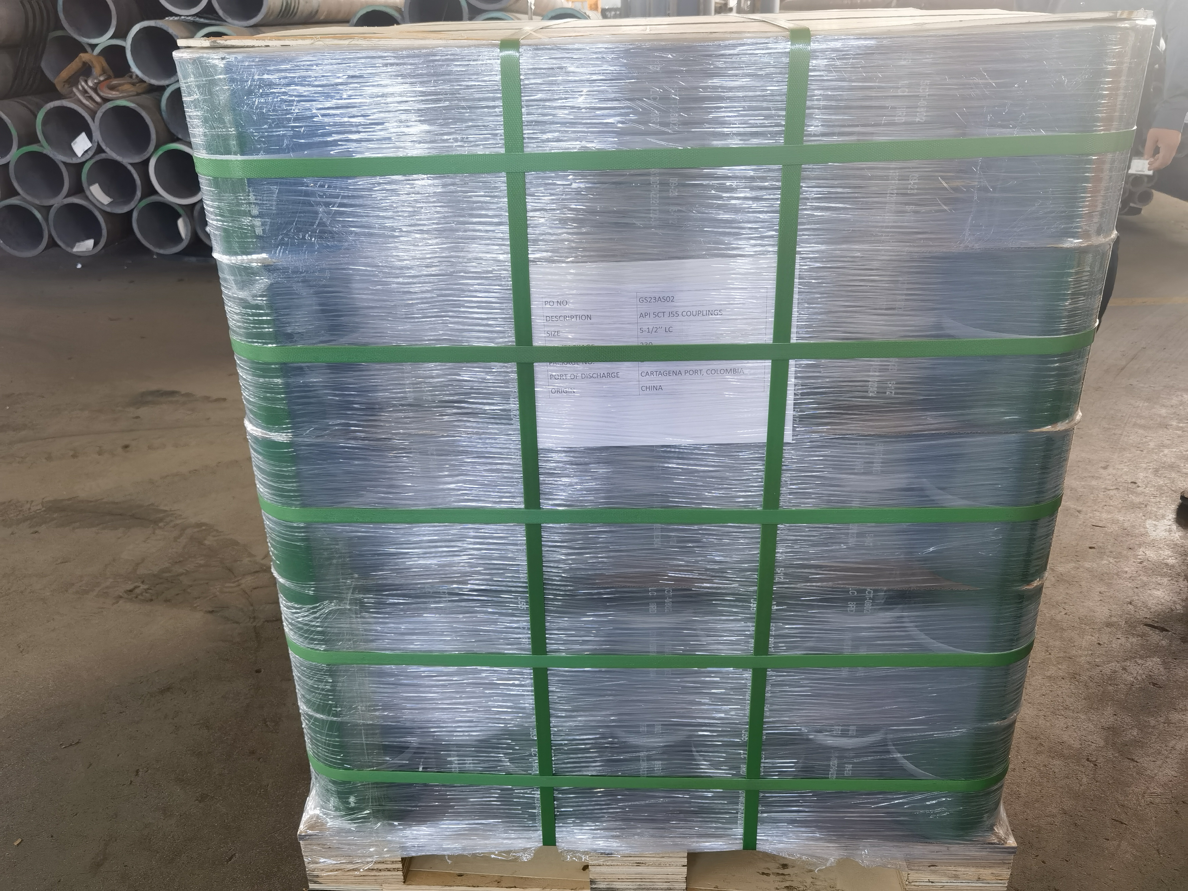 Shrink-wrapped and labelled coupling pallet from a ZC shipment — the English label reads "API 5CT J55 COUPLINGS 5-1/2 LC," identifying grade, size, and the long round thread (LC) coupling that forms the box half of an LTC connection.
API 5CT recognises two diameter classes of coupling, not three. Clause 8.5 defines the regular coupling (RC) at diameter W; clause 8.6 defines the special clearance coupling (SCC) at the reduced diameter Wc. Clauses 8.7 to 8.9 add combination, seal-ring and special-bevel couplings, but those vary the thread mix, the seal or the end profile — not the diameter class.
Regular coupling (RC), clause 8.5: Outside diameter W per Tables C.27 to C.30, and the default under 8.4.1 unless the purchase agreement says otherwise. Clause 8.5 requires the bearing face edges to be rounded or broken without materially reducing bearing face width b, "so that enough thickness is left to safely support the mass of the pipe on the elevator" — that face is a load-bearing surface, not a cosmetic chamfer.
What "LC" actually means: LC is not a coupling type. It is the long round thread casing coupling, the box half of an LTC connection, and SC on a round thread label is the short round coupling of STC. Table C.27 tabulates both against one outside diameter: at 7 inch, minimum coupling length NL is 184.15 mm (7.250 in) short and 228.60 mm (9.000 in) long, both on the same 200.03 mm (7.875 in) OD. STC to LTC buys thread engagement and joint strength through length, and no annular clearance whatsoever.
Special clearance coupling (SCC), clause 8.6: Reduced outside diameter Wc, for buttress casing and EU tubing only, all grades except Q125, and only when specified in the purchase agreement. What is reduced is coupling wall thickness, not thread engagement. Thread form, taper, pitch and engagement length are per API 5B and identical to the regular coupling — which is why an SCC makes up on the same pin. API 5CT quantifies the wall loss in Table C.7, "Critical Thickness for Couplings with API Threads", which defines critical thickness (6.3.2) as the thickness at the root of the thread at the coupling face and tabulates round thread, buttress regular and buttress special clearance side by side:
Critical thickness for casing couplings, API 5CT Table C.7 (and Table E.7 in inches).
| Label 1 | Buttress regular (mm) | Buttress special clearance (mm) | Long round LC (mm) | Short round SC (mm) | SCC loss vs BC |
|---|---|---|---|---|---|
| 4-1/2 | 11.35 | 6.58 | 12.04 | 11.74 | −42% |
| 5 | 12.17 | 6.76 | 12.98 | 12.47 | −44% |
| 5-1/2 | 12.28 | 6.81 | 13.06 | 12.57 | −45% |
| 6-5/8 | 11.91 | 6.96 | 12.90 | 12.32 | −42% |
| 7 | 13.46 | 7.11 | 14.43 | 13.72 | −47% |
| 7-5/8 | 13.61 | 8.84 | 14.55 | 13.87 | −35% |
| 8-5/8 | 15.29 | 8.94 | 16.43 | 15.54 | −42% |
| 9-5/8 | 15.29 | 8.94 | 16.69 | 15.60 | −42% |
| 10-3/4 | 15.29 | 8.94 | — | 15.70 | −42% |
Read the 7-inch row. The regular buttress coupling has 13.46 mm (0.530 in) of steel at the thread root; the special clearance version has 7.11 mm (0.280 in) — a 6.35 mm (0.250 in) reduction, 47% of the section, in exchange for 12.71 mm (0.500 in) off the outside diameter. The loss is consistent across the range at roughly 42% to 47%, with 7-5/8 the mildest at 35%. That is the honest description of the trade: you are not giving up thread engagement, you are giving up wall in the box, and the coupling becomes the thinnest load-bearing section in the connection.
Two consequences follow from the wall. The reduced section governs internal pressure and tensile capacity, so the string design has to be rerun on the SCC geometry rather than carried over — the Joint Strength Calculator → gives connection tensile capacity for comparison. And because 6.4.4 calculates minimum Charpy absorbed energy for a coupling from the critical thickness, an SCC's required impact energy is lower than the regular coupling's at the same grade. The component is genuinely thinner and its acceptance criteria move with it.
5. There Is No PSL in API 5CT — Name the Clause Instead
API 5CT 11th Edition has no product specification level. The phrase does not occur anywhere in the standard. Every "PSL" string in it is an end-finish code — PSL and PSLB — inside the dimension tables of Annexes C and E, and the phrase "product specification level" does not occur anywhere in the document. PSL 1 and PSL 2 are API 5L constructs, and API 5L is line pipe. A PO line reading "API 5CT L80 couplings, PSL-2" asks for something the specification cannot supply; a careful mill queries it, a busy one ignores it, and either way the requirement you wanted never reaches the manufacturing plan.
"PSL-2" on an API 5CT purchase order is not a requirement — it is a blank. The mill can ship a fully conforming coupling with no impact test, no NDE, no product analysis and a 3.1 certificate, and the PO gives you nothing to reject it with. Name the clauses.
Everything buyers reach for when they write "PSL-2" exists in API 5CT under its own clause number, and each one is orderable.
What to write instead of "PSL-2", by requirement.
| What you want | API 5CT clause | What it actually gives you on a coupling |
|---|---|---|
| Impact testing | 6.4 (requirement), 9.7 (method), A.9 (SR 16) | 6.4.4 calculates minimum absorbed energy from the specified maximum yield strength and the critical thickness of the coupling, with Tables C.12 and C.13 as the floor. 6.4.3 sets a flat 20 J transverse / 27 J longitudinal minimum for J55 and K55 couplings at all wall thicknesses. H40 has no mandatory requirement unless A.9 (SR 16) is specified (6.4.2). Frequency per Table C.16 |
| Nondestructive examination | 9.15.11 with Table C.37, or A.3 (SR 2) | 9.15.11.1 covers coupling stock NDE for outside-surface imperfections by ultrasonic, flux leakage, eddy current or magnetic particle testing to the acceptance level in Table C.38. Table C.37 states when it is mandatory. Grades L80 13Cr, C90, T95, C110 and Q125 are carved out into the stricter 9.15.12, which adds through-wall and inside-surface UT |
| Hardness | 6.7.1 with Table C.5, frequency 9.6.3 / 9.6.6 / 9.6.7 | Table C.5 caps the mean hardness. 6.7.1 adds the single-reading rule: L80 rejects any individual indentation above 24.0 HRC; C90 and T95 reject above 27.0 HRC and retest between 25.4 and 27.0 HRC. Frequency for L80 coupling stock, blanks and material is the same as tensile testing (9.6.3); for C90, T95 and C110 it is 9.6.6, four quadrants, on the highest-surface-hardness piece in the lot; Q125 is 9.6.7 |
| Traceability | 5.4.1, 5.4.2 | 5.4.1 makes full tracing to heat, lot and all chemical and mechanical results mandatory for C110 and Q125, and purchaser-specified for every other grade — so on L80 or T95 it is a PO item. 5.4.2 mandates unique serialisation of every length of coupling stock, coupling material and coupling blank for C90, T95, C110 and Q125, with heat-treat lots uniquely numbered and process-run pieces sequentially numbered |
| Maximum yield control | Table C.5 column 5 | Already mandatory, not an option. L80 is 552 to 655 MPa (80.0 to 95.0 ksi), T95 is 655 to 758 MPa (95.0 to 110.0 ksi), P110 is 758 to 965 MPa (110.0 to 140.0 ksi). No PSL tier is involved |
Read that as a procurement document, not a reference: three of the five rows are conditional on the purchase agreement, so the difference between a coupling with a full test history and one without is four clause citations on a PO line. The last row was never a PSL matter at all — API 5CT has always capped maximum yield for L80, T95, C110 and Q125 in Table C.5, and the widely repeated claim that "PSL-2 controls maximum yield" is describing API 5L.
6. Sour Service Coupling Requirements
API 5CT's own controls on a sour-service coupling are these:
- Grade: L80 Type 1, C90, T95, or C110, matching the string per clause 8.1 b) — there is no clause 8.2 substitution for any of them
- Maximum hardness: the API 5CT Table C.5 maximum mean for the grade, per footnote c — 23.0 HRC (241 HBW) for L80, 25.4 HRC (255 HBW) for C90 and T95, 29.0 HRC (279 HBW) for C110 — applied to pipe body AND coupling. Clause 6.7.1 adds the single-indentation rule on top: an L80 piece is rejected if any one reading exceeds 24.0 HRC, and a C90 or T95 piece is rejected above 27.0 HRC and retested between 25.4 and 27.0 HRC
- SSC testing: API 5CT 6.14 / 9.10 covers C90, T95 and C110 only, with A.18 (SR 46) available to increase sampling on C90 and T95. L80 couplings get no SSC test under API 5CT; any SSC or HIC testing on an L80 coupling is a project-specification overlay
- Chemical analysis: product analysis with controlled sulphur and phosphorus
- Traceability: mandatory full tracing under 5.4.1 for C110 only; on L80, C90 and T95 it is purchaser-specified, so write it in. Serialisation of coupling stock, coupling material and coupling blanks under 5.4.2 is mandatory for C90, T95 and C110 — and not for L80
- MTC: EN 10204 3.2
Critical point: Coupling hardness must be independently verified — the coupling is machined from different stock than the pipe body, heat-treated on its own schedule, and API 5CT gives it its own test frequency (9.6.3 for L80, 9.6.6 for C90, T95 and C110). Do not infer that a coupling meets the Table C.5 mean-hardness limit from pipe body hardness data.
Coupling hardness must be independently tested — it cannot be inferred from the pipe body MTC. Couplings are machined from coupling stock, coupling material or blanks, heat-treated separately, and cool at a different rate from a full-length tube. We have seen an L80 order where the pipe body mean hardness sat around 19 HRC and the coupling mean came back above the 23.0 HRC that Table C.5 caps L80 at — one reading over 24.0 HRC is an outright rejection under 6.7.1, on the coupling alone, with the pipe entirely conforming. Always require a separate hardness test record for the coupling, reported as mean values with the individual indentations tabulated, because the mean and the single-reading limits are two different acceptance criteria and only the tabulation shows both.
When NOT to Use Standard or Special Clearance Couplings
| Scenario | Risk | Correct Approach |
|---|---|---|
| Sour service string with standard sweet-service couplings | SSC cracking at the connection — the highest-stress point in the string | Specify L80 Type 1, C90, T95 or C110 couplings and require hardness reported against the Table C.5 mean limit with individual indentations tabulated against the 6.7.1 single-reading rule |
| Special clearance coupling without recalculating on the reduced wall | The SCC critical thickness is 35–47% below the regular coupling (Table C.7) — it is the thinnest load-bearing section in the connection | Recalculate tensile and internal pressure capacity on the Wc geometry and the Table C.7 critical thickness before specifying |
| Couplings ordered without naming the test clauses (or with "PSL-2", which API 5CT has no concept of) | No impact test, no NDE, no product analysis, no traceability — and a conforming shipment | Cite 6.4 with A.9 (SR 16) for impact, 9.15.11 with Table C.37 or A.3 (SR 2) for NDE, and 5.4.1 for traceability |
| Reduced-OD couplings assumed available on a long round or Q125 string | Clause 8.6 scopes special clearance to buttress casing and EU tubing, excludes Q125, and Table C.28 tabulates no Wc above 10-3/4 | Decide the connection before the clearance problem is discovered — on LTC or Q125 or 11-3/4-and-larger, the clearance has to come from the hole |
| Coupling grade assumed equal to pipe body | Coupling from different heat — may be lower grade in practice | Require separate coupling MTC showing grade, heat number, and test results |
| BTC couplings specified without checking wellbore clearance | Regular coupling OD runs 19.05 mm larger than pipe body at 4-1/2 (133.35 vs 114.30) to 34.92 mm larger at 18-5/8 (508.00 vs 473.08) — it may not pass a liner hanger | Verify coupling OD against every downhole equipment bore diameter before ordering |
| Reusing pulled couplings without inspection | Thread wear and SSC damage not visible to eye | Full API 5B thread gauge inspection + hardness test before any coupling reuse |
7. Purchase Order Specification
 Strapped coupling pallets loaded into a shipping container on a ZC order — couplings ship as their own line item so they can be thread-inspected before the string is run.
When ordering couplings as part of a casing or tubing string, specify:
Procurement trap — coupling grade not explicitly matched:
Wrong PO: "Supply L80 casing couplings, BTC, 7-inch 26 lb/ft." No sour service requirements stated.
What ships: L80 BTC couplings meeting the dimensional and mechanical requirements of API 5CT, with hardness reported only to the extent the standard requires, and without an EN 10204 3.2 certificate. Technically compliant with the PO as written.
Correct PO: "Supply L80-1 casing couplings, BTC, 7-inch 26 lb/ft, for sour service. Coupling hardness shall be reported against the API 5CT Table C.5 limit of 23.0 HRC / 241 HBW maximum mean, with individual readings tabulated. Any project hardness limit tighter than Table C.5 is stated here as a project requirement and shall be reported separately from the API acceptance criterion. MTC: EN 10204 3.2. Separate MTC for coupling heat required."
Failure Modes
Failure Mode 1 — Sweet-service coupling in sour string
Mechanism: Standard J55 or N80 coupling installed in an L80 sour service string. The coupling has no hardness control, and HRC may be 28–32. Under H₂S partial pressure, SSC initiates at the connection thread roots within weeks of production start.
Diagnostic: Connection leak or tensile failure shortly after production startup in a sour well. MTC review shows the couplings were supplied to a grade that API 5CT places no hardness limit on. Coupling hardness testing on the pulled string returns values well above the 23.0 HRC that Table C.5 caps L80 at.
Fix: Pull the affected string section. Re-specify all couplings as L80-1 or T95 and require tabulated coupling hardness results against the Table C.5 limit on the next purchase order. Where the project imposes a tighter limit or an SSC test, write both out in full rather than abbreviating to a code.
Failure Mode 2 — Special clearance coupling tensile overload
Mechanism: An SCC is specified to pass a tight liner hanger bore. Thread engagement is unchanged — the thread form and length are per API 5B and identical to the regular coupling — but the coupling wall is not. At 7 inch, Table C.7 puts the critical thickness at 7.11 mm (0.280 in) against 13.46 mm (0.530 in) regular, so the box becomes the thinnest load-bearing section in the connection. If the string design load is carried over from the regular coupling, the coupling wall, not the thread, is the section that yields.
Diagnostic: Connection parting or box swelling during running, with the threads gauging in tolerance afterwards. Engineering review finds the design was never rerun on the Wc geometry and the Table C.7 critical thickness. A second tell: the coupling's Charpy acceptance value was also carried over, when 6.4.4 calculates required absorbed energy from critical thickness and therefore sets a lower requirement for the SCC at the same grade.
Fix: For every SCC application, require the manufacturer to state tensile, compressive and internal pressure capacity for the Wc geometry, and require the Charpy result against the SCC critical thickness rather than the regular one. Verify both against worst-case string design loads before running. On the rack, confirm the black centre band required by 10.4.4 — it is the only visual difference between an SCC and a regular coupling.
Failure Mode 3 — Coupling hardness assumed from pipe body MTC
Mechanism: The MTC shows pipe body hardness around 19 HRC on all records. The procurement team assumes the couplings are equally clear. The couplings are from separate coupling stock with no separate hardness test. Actual coupling mean hardness is 24.5 HRC — above the 23.0 HRC mean that Table C.5 caps L80 at, and above the 24.0 HRC single-reading rejection threshold in 6.7.1. SSC initiates at the connection in a sour well within months.
Diagnostic: Connection SSC cracking with the pipe body intact. Hardness testing of a pulled coupling returns a mean above the Table C.5 limit for the grade. The MTC shows no separate coupling hardness record, which is itself the finding — 9.6.3 requires hardness testing of coupling stock, blanks and material at the same frequency as tensile testing on L80.
Fix: For all sour service orders, require a separate coupling heat MTC that includes: heat number, product analysis, and coupling hardness test results (HRC or HV). Reject any coupling delivery where the coupling MTC is absent or references the pipe body heat number rather than the coupling stock heat number.
- Standard: API 5CT / ISO 11960
- Grade: [matching pipe grade]
- Pipe OD and weight (lb/ft): determines coupling dimensions
- Connection type: STC / LTC / BTC / EUE / NUE
- Coupling type: Regular coupling (RC, clause 8.5) or Special Clearance coupling (SCC, clause 8.6). SCC is buttress casing and EU tubing only, excludes Q125, and is tabulated only to 10-3/4 casing and 3-1/2 EU tubing
- Alternative coupling grade, if wanted: cite the clause — 8.2.5, 8.2.9 or 8.2.10 — because none of them applies unless specified in the purchase agreement
- Impact testing: API 5CT 6.4, tested to 9.7, with A.9 (SR 16) if you want testing rather than qualification by documented procedure. Frequency per Table C.16
- Nondestructive examination: 9.15.11 to the Table C.38 acceptance level, or A.3 (SR 2) where the supplementary requirement applies
- Traceability: 5.4.1 full tracing to heat and lot — a purchaser-specified item on every grade except C110 and Q125
- Quantity: typically 1 coupling per pipe joint + 5-10% spare
- Sour service requirements: name the grade, the hardness acceptance criterion, and any project-specified SSC (NACE TM0177) or HIC (NACE TM0284) testing in full
- Hardness: report against API 5CT Table C.5 for the grade — 23.0 HRC / 241 HBW maximum mean for L80
- MTC: EN 10204 3.1 or 3.2
- Marking: per the Table C.43 sequence — manufacturer's mark, 5CT, date of manufacture, size designation, grade symbol, thread type, plus 5.4.2 serialisation on C90, T95, C110 and Q125. Table C.43 does not require a heat number on a coupling, so if you want heat identity on the piece rather than only on the certificate, specify it as an additional marking under 10.1.10
- Colour identification: per 10.4 — 10.4.3 for loose couplings, and the black centre band of 10.4.4 if special clearance couplings are supplied
Typical quantity calculation: Number of couplings = number of pipe joints × 1.05 (5% spare for damaged or rejected couplings during running)
ZC Steel Pipe supplies API 5CT couplings for all standard casing and tubing sizes in all grades. Couplings are typically supplied as part of a complete pipe string package. Contact us with your pipe OD, weight, grade, connection type, and quantity for availability and pricing.
Frequently Asked Questions
What is an API 5CT coupling?
An API 5CT coupling is a short cylindrical sleeve with internal threads machined at both ends, used to connect two joints of threaded casing or tubing pipe. The pin end of one pipe joint is made up into one end of the coupling, and the pin end of the next joint is made up into the other end. The coupling provides the mechanical connection and sealing between joints. API 5CT and API 5B define the dimensional requirements, thread form, and mechanical properties for standard casing and tubing couplings.
What are the OD dimensions for BTC casing couplings?
Buttress coupling outside diameter W is read from API 5CT Table C.28. For 5-1/2 inch casing it is 160.02 mm (6.300 in); for 7 inch, 200.03 mm (7.875 in); for 9-5/8 inch, 269.88 mm (10.625 in); for 13-3/8 inch, 365.12 mm (14.375 in). Table C.27 gives the same regular W for round thread couplings at every one of those sizes, so switching from buttress to long round buys no annular clearance on its own. Where clearance is short, Table C.28 tabulates a special clearance diameter Wc from 4-1/2 through 10-3/4 only, which is 187.32 mm (7.375 in) at 7 inch. Always verify coupling OD against the wellbore diameter and any centralizer or cement head clearance requirement.
Must couplings be the same grade as the pipe?
API 5CT 8.1 b) requires couplings to be of the same grade and type as the pipe body, and 8.1 c) requires the same heat treatment, except as provided in clause 8.2. Clause 8.2 is a named list of substitutions rather than a general rule that any higher grade is acceptable: 8.2.2 allows J55 or K55 couplings on J55 pipe, 8.2.6 allows N80 Type 1 or N80Q couplings on normalized N80 Type 1 pipe, 8.2.5 furnishes L80 Type 1 couplings on J55 and K55 buttress casing when specified, 8.2.9 furnishes P110 couplings on N80 Type 1 and N80Q buttress casing when specified, and 8.2.10 furnishes Q125 couplings on P110 buttress casing when specified. Each of those upward moves happens only when it is specified in the purchase agreement, so write it on the purchase order rather than assuming the mill will apply it.
What does LC mean on a coupling label, and is it stronger than SC?
LC is the long round thread casing coupling, which is the box half of an LTC connection, and SC is the short round thread casing coupling used on an STC connection. They are not strength options added to some other connection. API 5CT Table C.27 tabulates both against the same outside diameter W: at 7 inch, minimum coupling length NL is 184.15 mm (7.250 in) short and 228.60 mm (9.000 in) long, both on a 200.03 mm (7.875 in) OD. The extra tensile capacity of LTC therefore comes from coupling length and thread engagement at unchanged outside diameter, which is why going from STC to LTC gains joint strength but gains no annular clearance.
What is the difference between a regular coupling and a special clearance coupling?
A regular coupling has the outside diameter W tabulated in API 5CT Tables C.27 to C.30, and clause 8.4.1 makes it the default unless the purchase agreement says otherwise. A special clearance coupling has the reduced outside diameter Wc of Table C.28 or Table C.30, so it will pass a restriction a regular coupling will not. What changes is coupling wall thickness, not thread engagement: the thread form and length are per API 5B and are unchanged, and API 5CT quantifies the wall loss directly in Table C.7, where the critical thickness of a 7 inch buttress coupling falls from 13.46 mm (0.530 in) regular to 7.11 mm (0.280 in) special clearance. Clause 8.6 also limits the option to buttress casing and EU tubing, excludes Grade Q125, and Table C.28 tabulates Wc only from 4-1/2 through 10-3/4.
Can couplings be reused after a string is pulled?
Couplings can be reused if they pass inspection after the string is pulled — but this requires careful evaluation. Thread gauging must confirm threads are within tolerance. Any galling, corrosion damage, or thread wear detected during inspection requires the coupling to be replaced. For premium connection couplings, manufacturer inspection criteria apply. For sour service couplings, additional inspection for SSC cracking is required before reuse. Never reuse couplings that show visible damage, cracking, or thread wear beyond API 5B tolerance.
What marking is required on API 5CT couplings?
Coupling marking follows the sequence in API 5CT Table C.43, which for the coupling columns calls for the manufacturer's name or mark, 5CT, the date of manufacture, the size designation, the grade symbol (L for L80 Type 1, T for T95, P for P110, Q for Q125, L13 for L80 13Cr), the thread type, and the serial number for Grades C90, T95, C110 and Q125 under 5.4.2. Note what is not on that list: Table C.43 does not require the mass designation or a heat number on a coupling, so heat traceability comes from clause 5.4 and the certificate rather than from the stencil. Colour identification is mandatory under 10.4 — loose couplings are painted per 10.4.3, and a special clearance coupling carries a black band around the centre in addition to the grade colours under 10.4.4, which is the only way to tell it from a regular coupling on the rack.
What is the wall thickness of a casing coupling?
The figure that matters is not the blank wall but the critical thickness, which API 5CT 6.3.2 defines as the thickness at the root of the thread at the coupling face and tabulates in Table C.7. For 7 inch casing that is 13.46 mm (0.530 in) for a buttress regular coupling, 14.43 mm (0.568 in) for a long round coupling, 13.72 mm (0.540 in) for a short round coupling, and 7.11 mm (0.280 in) for a buttress special clearance coupling. Table C.7 notes that the coupling blank thickness is greater than these values because of thread height and machining allowance. Outside diameters and lengths come from Tables C.27 to C.30.