3LPE, FBE, and 3LPP are the three dominant external coating systems for steel line pipe. FBE (Fusion Bonded Epoxy) is a single-layer thermoset epoxy of 300–500 microns rated to 95°C continuous service, primarily used as a primer or in subsea pipelines with concrete weight coating. 3LPE (Three-Layer Polyethylene) adds adhesive and polyethylene layers over an FBE primer for total thickness of 2.5–4.5 mm, rated to 80°C — the global standard for buried onshore pipelines. 3LPP (Three-Layer Polypropylene) substitutes polypropylene for the outer layer, extending continuous service temperature to 110°C standard or 130–140°C for high-temperature formulations, used in subsea flowlines and hot oil service.
ZC Steel Pipe supplies API 5L line pipe with 3LPE, FBE, and 3LPP external coating systems for oil, gas, and water transmission projects. This guide covers the technical basis for each coating system, applications where each is correct, temperature and mechanical limits, applicable standards, and the items to specify on a coated pipe purchase order.
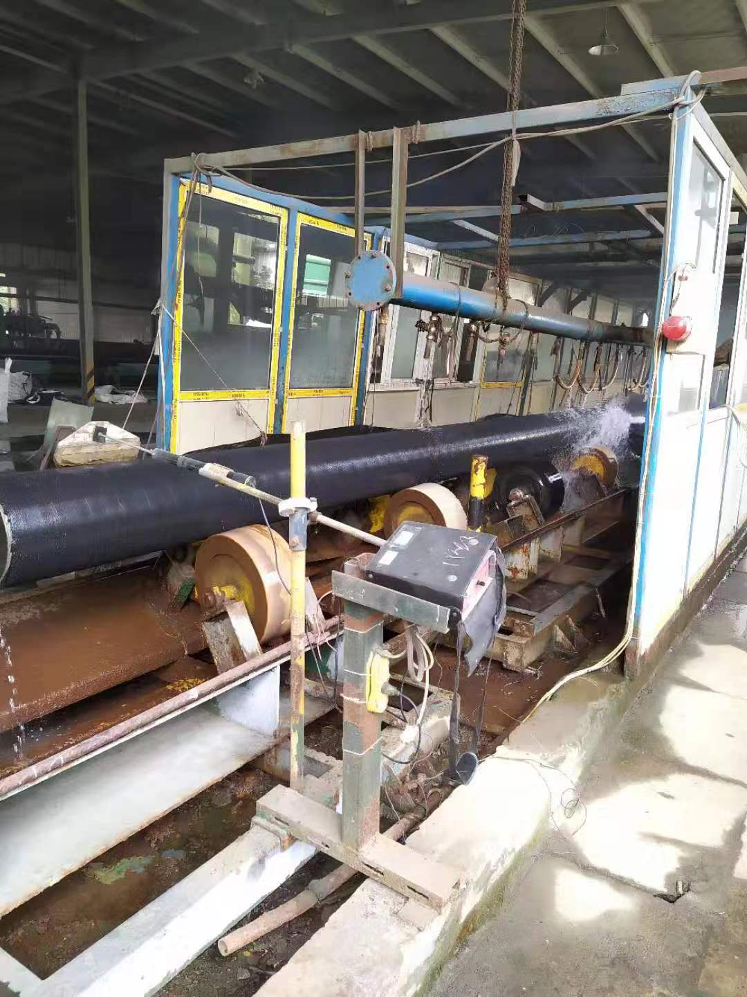 A ZC coating line: black-coated pipe rotating through the water-spray cooling station.
Quick Answer
For buried onshore pipelines up to 80°C, specify 3LPE. For hot service above 80°C — subsea flowlines, hot oil, EOR injection — specify 3LPP (110°C standard, 130–140°C for high-temperature formulations). Use FBE alone only where a concrete weight coat or a subsequent three-layer system provides the mechanical protection bare FBE lacks.
| System | Thickness | Max continuous temp | Specify when |
|---|---|---|---|
| FBE | 300–500 μm | 95°C | Subsea under concrete weight coat, internal, or as the primer layer |
| 3LPE | 2.5–4.5 mm | 80°C | Buried onshore oil, gas, and water transmission lines |
| 3LPP | 2.5–5.0 mm | 110–140°C | Hot service and subsea flowlines above 80°C |
What we see on orders: On a West Africa onshore gas project, the PO specified "3LPE per ISO 21809-1" for 24-inch pipe without stating a minimum coating thickness. The mill applied 3.0 mm — the ISO 21809-1 minimum for OD > 323 mm. The project engineer had specified 3.5 mm on the project datasheet, but the datasheet was never attached to the PO. The pipe arrived and passed all ISO acceptance criteria. Upgrading coating thickness in the field is not possible; the project had to accept 3.0 mm or order replacement pipe with a 6-week delay and 15% premium. Minimum thickness must be explicitly stated on the PO, not left to ISO default.
1. The Three Main External Coating Systems
FBE — Fusion Bonded Epoxy
FBE is a 300–500 micron thermoset epoxy powder coating applied electrostatically to a preheated, blast-cleaned pipe surface. The powder melts, flows, and cures to form a continuous, tightly adhered coating that bonds chemically to the steel. FBE provides:
- Adhesion — the highest of the three coating types
- Cathodic disbondment resistance — critical for pipelines with cathodic protection
- Chemical resistance — withstands soil chemicals and process fluids that contact the pipe
- Temperature resistance — up to approximately 95°C continuous
FBE's limitation is mechanical protection. The single thin layer provides minimal resistance to impact and abrasion — a stone dropped from 50 cm can crack FBE. This makes bare FBE unsuitable for buried pipelines handled with excavators or installed in rocky soil.
FBE is used for:
- Subsea pipelines that will receive concrete weight coating (the concrete provides mechanical protection)
- Factory-applied internal coating for corrosion control
- Pipe that will receive 3LPE or 3LPP coating (FBE is the primer layer in both systems)
- Sections where heat-shrink sleeve or other field joint coating will be applied
3LPE — Three-Layer Polyethylene
3LPE is a 2.5–4.5 mm composite coating built on an FBE primer with two additional layers:
- Layer 1 (primer): FBE — 150–300 microns — adhesion and cathodic protection
- Layer 2 (adhesive): Copolymer adhesive — 150–300 microns — bonds FBE to polyethylene
- Layer 3 (outer): High-density polyethylene (HDPE) — 2–3.5 mm — impact and abrasion resistance
The polyethylene outer layer transforms the coating from a chemical barrier into a mechanical barrier capable of withstanding the stresses of installation by open trench in normal soil conditions.
3LPE is used for:
- Buried onshore oil and gas pipelines — the standard choice for most onshore projects globally
- Gas distribution pipelines buried in suburban and rural areas
- Pipelines installed by open cut in normal to moderately rocky soil
- Water transmission pipelines, buried
- Temperature range: -40°C to +80°C continuous service
3LPP — Three-Layer Polypropylene
3LPP uses the same three-layer architecture as 3LPE but substitutes polypropylene for polyethylene as the outer layer. Polypropylene's higher melting point and mechanical properties at elevated temperature extend the coating's service range:
- Standard 3LPP: continuous service to 110°C
- High-temperature 3LPP: continuous service to 130–140°C
- Impact resistance: slightly lower than 3LPE at ambient temperature, but superior above 70°C where polyethylene softens
3LPP is used for:
- Subsea and offshore production flowlines where process temperature exceeds 3LPE's limit
- Hot oil pipelines and EOR (enhanced oil recovery) injection lines
- High-temperature gas gathering where wellhead temperatures are elevated
- Deepwater pipelines where low ambient temperature and high process temperature both apply
3LPP has lower impact resistance than 3LPE below 10°C — polypropylene becomes brittle at low ambient temperatures where polyethylene retains ductility. If the coating is selected for elevated operating temperature (3LPP) but installation takes place in winter at sub-10°C, mechanical damage risk during handling is higher than for 3LPE. For cold-climate projects, confirm the PP outer layer grade is rated for the minimum installation temperature as well as the maximum operating temperature — these are two separate data sheet values.
What we ship most in coated line pipe: 3LPE is by far the most-ordered coating in our line-pipe shipments. Recent examples include OD 12-inch X65Q 3LPE line pipe to Africa, specified with a non-slip granular topcoat for marine handling, and 3,000 pcs of X70Q sour-service pipe with 3 mm 3LPE to Africa. Across African onshore projects, 3 mm 3LPE per DIN 30670 is the default we see specified for direct-burial service; see more in our project records.
2. Coating Selection Summary Table
| Property | FBE | 3LPE | 3LPP |
|---|---|---|---|
| Coating layers | 1 | 3 | 3 |
| Total thickness | 300–500 μm | 2.5–4.5 mm | 2.5–5.0 mm |
| Max continuous temperature | 95°C | 80°C | 110–140°C |
| Impact resistance | Low | High | High (lower than 3LPE at ambient) |
| Abrasion resistance | Low | High | High |
| Cathodic disbondment | Excellent | Good | Good |
| Adhesion to steel | Excellent | Good (via FBE primer) | Good (via FBE primer) |
| Subsea / CWC compatible | Yes | Limited | Yes |
| Primary standard | ISO 21809-2 | ISO 21809-1 | ISO 21809-1 |
| Relative cost | Baseline | 2–3× FBE | 3–4× FBE |
| Typical application | Subsea, internal, primer | Buried onshore | Hot service, subsea flowlines |
The table above covers the primary selection factors, but two columns warrant emphasis: the temperature ceiling for 3LPE (80°C) is a hard limit in buried service, not a design margin. And the subsea/CWC compatibility column reflects that 3LPE under concrete weight coating is a specific design risk — the concrete impingement during laying can damage the PE layer in ways that are undetectable before immersion.
For the underlying line pipe grade specifications — including X65 and X70, the grades most commonly ordered for coated service — see the API 5L specification tables →
To verify the base pipe design pressure, use the Pipeline Design Calculator →
3. Application Decision Guide
| Application | Correct Coating |
|---|---|
| Buried onshore gas or oil pipeline | 3LPE |
| Rocky soil, aggressive terrain | 3LPE with enhanced thickness (3.5–4.5 mm) |
| High-temperature onshore (>80°C) | 3LPP |
| Subsea with concrete weight coating | FBE |
| Subsea flowline without CWC, ambient temp | 3LPE or FBE per project spec |
| Subsea flowline, high process temperature | 3LPP |
| Internal corrosion control | FBE (internal) |
| Arctic burial (-40°C operating) | 3LPE — confirm PE grade for low-temperature ductility |
| Water transmission, buried | 3LPE |
| Steam injection, EOR | 3LPP high-temperature grade |
Most projects fit cleanly into one row of this table. Where they do not — for example, a buried pipeline at 70–80°C that operates in cold-climate winter installations — the correct answer requires checking both the operating temperature data sheet and the installation temperature specification against the PP grade rating.
4. Applicable Coating Standards
External coating selection is governed primarily by ISO 21809 series and supplementary regional standards:
- ISO 21809-1 — External coatings for buried or submerged pipelines (3LPE and 3LPP). The dominant standard for new projects internationally.
- ISO 21809-2 — External coatings for buried or submerged pipelines (FBE).
- ISO 21809-3 — Field joint coatings, applied at girth welds in the field.
- DIN 30670 — Polyethylene coatings on steel pipes and fittings. Widely specified in European, Middle East, and African projects.
- DNV-ST-F101 — Submarine pipeline systems. Adds offshore-specific coating performance requirements.
- NACE SP0490 — Holiday testing of new protective coatings on conductive substrates.
- API RP 5L2 — Internal coating of line pipe for non-corrosive gas transmission (relevant when internal FBE is specified).
Project specifications often add requirements beyond these standards, particularly minimum coating thickness, peel adhesion test values (typically 100–150 N/cm at 23°C for 3LPE), cathodic disbondment maximum radius, and holiday test voltage. The ISO standard sets minimums — project specs routinely tighten them for aggressive environments or high-consequence pipelines.
5. Field Joint Coating
Wherever pipe sections are welded together in the field, the coating must be continued across the weld area (field joint). Field joint coating is a separate specification from the factory coating and must be compatible with it:
- FBE main coat → FBE field joint or heat-shrink sleeve
- 3LPE main coat → heat-shrink sleeve, injection-moulded polypropylene, or infra-red heated shrink sleeve
- 3LPP main coat → injection-moulded polypropylene or infra-red heated polypropylene sleeve
Field joint coating quality is critical. The majority of corrosion failures on coated pipelines originate at field joints where coating application was poor — typically due to insufficient surface preparation, incorrect application temperature, or sleeve installation defects. Specify the field joint coating system on the purchase order and confirm it is compatible with the factory coating type and the field welding conditions. A 3LPP factory coat paired with a heat-shrink sleeve designed for 3LPE service temperatures will debond at sustained operating temperature above 80°C.
6. Holiday Testing and Coating Quality Control
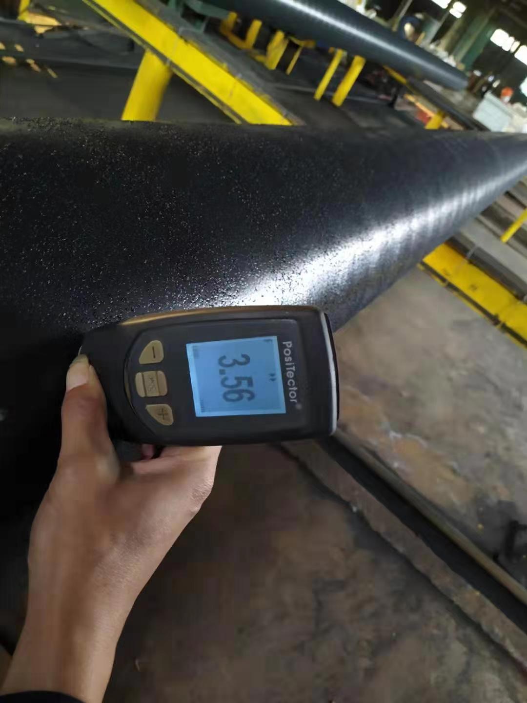 Coating-thickness verification with a PosiTector gauge on 3LPE-coated pipe.
Holiday testing (spark testing) is the primary electrical test for detecting coating defects before dispatch. A high-voltage electrode is passed over the entire coated surface — any pinhole, void, or area of insufficient thickness triggers a detectable spark (a "holiday").
Holiday test voltage is calculated from coating thickness:
- 3LPE 2.5–3.0 mm: approximately 9–12 kV
- 3LPE 3.0–4.0 mm: approximately 12–18 kV
- FBE 300–500 μm: approximately 1.5–3 kV
- 3LPP standard: 18–25 kV depending on thickness
Acceptance criteria are zero holidays after final repair, or a maximum number of repaired holidays per joint as specified in the purchase order. Additional quality control tests typically required by project specifications include peel adhesion (per ISO 21809-1), cathodic disbondment (28-day test), indentation hardness, and impact resistance.
Holiday Test Voltage Calculation
ISO 21809-1 Annex H specifies the holiday test voltage formula as V_test = 7,500 × √t, where t is the total coating thickness in millimetres. The table below shows calculated test voltages for common 3LPE and FBE thickness levels:
| Coating | Thickness (mm) | Calculation | Test Voltage |
|---|---|---|---|
| 3LPE standard | 2.5 | 7,500 × √2.5 | 11,860 V ≈ 12 kV |
| 3LPE enhanced | 3.5 | 7,500 × √3.5 | 14,030 V ≈ 14 kV |
| 3LPE rocky terrain | 4.5 | 7,500 × √4.5 | 15,910 V ≈ 16 kV |
| FBE 400 µm (0.4 mm) | 0.4 | 7,500 × √0.4 | 4,740 V ≈ 5 kV |
Specifying only "holiday test per ISO 21809-1" without stating the thickness on the PO means the holiday voltage is calculated from the ISO minimum thickness for the pipe OD, not from the project-specified thickness. For a 24-inch pipe at ISO minimum 3.0 mm, that gives ≈ 13 kV; at the project-specified 3.5 mm, it should be ≈ 14 kV. If the mill applies 3.0 mm and tests at 13 kV, holidays that would be detected at 14 kV may be missed. This is another reason minimum thickness must be explicit on the PO.
7. How to Specify Coated Line Pipe on a Purchase Order
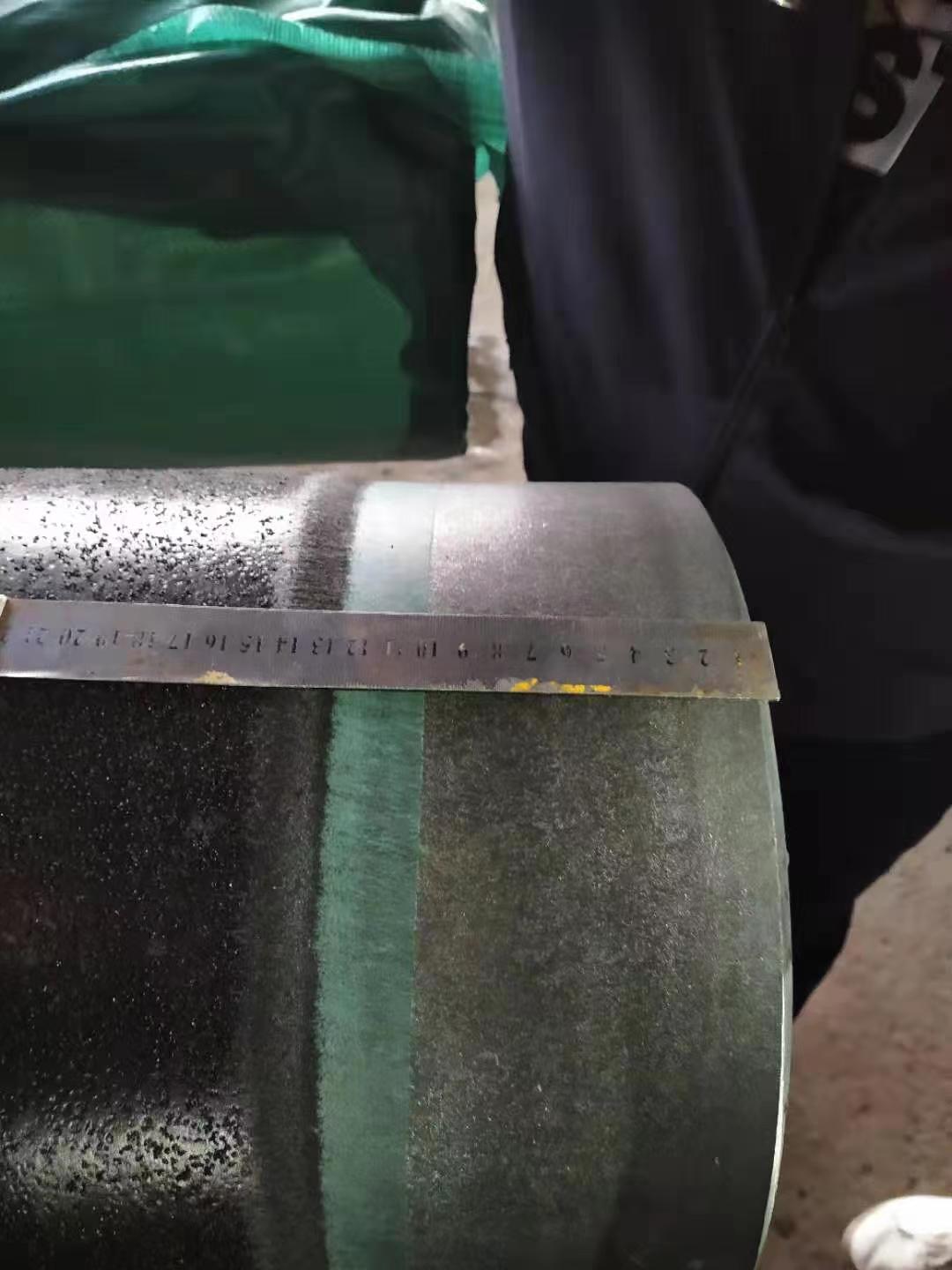 Checking coating geometry at a 3LPE-coated pipe end against a steel ruler.
Include the following items on every coated pipe purchase order:
- Coating type: FBE, 3LPE, or 3LPP
- Applicable standard: ISO 21809-1, ISO 21809-2, or DIN 30670
- Minimum coating thickness: by pipe OD range (per ISO 21809 minimums, or project-specific enhanced values)
- Holiday test voltage: per ISO 21809 or project specification
- Adhesion test: minimum peel strength in N/cm at specified temperature
- Cathodic disbondment test: test conditions and maximum disbondment radius
- Cutback length: bare steel at pipe ends for field welding (typically 100–150 mm each end)
- Surface preparation: Sa 2.5 blast cleaning to ISO 8501-1, with surface profile typically 40–100 μm
- Internal coating: if required, specify separately (typically internal FBE for gas transmission)
- Material test certificate: EN 10204 3.1 or 3.2 per project requirement
Procurement trap — exactly what goes wrong without explicit PO language:
Wrong PO: "API 5L X65M PSL2, 24-inch × 14.3 mm, 3LPE coated per ISO 21809-1."
What ships: The mill applies 3.0 mm — the ISO 21809-1 minimum for OD > 323 mm. No peel adhesion test value is specified, so it defaults to ISO minimum at room temperature only. No cathodic disbondment criterion is stated. Holiday voltage is calculated from 3.0 mm (≈ 13 kV), not from 3.5 mm (≈ 14 kV). The pipe is fully ISO-compliant and the mill has done nothing wrong — but the pipe does not meet the project datasheet.
Correct PO additions: "3LPE minimum 3.5 mm total thickness; peel adhesion ≥ 150 N/cm at 23°C per ISO 21809-1 Clause 9; cathodic disbondment maximum 8 mm radius at 65°C; holiday test per ISO 21809-1 Annex H at V = 7,500 × √t V where t = actual measured thickness."
ZC Steel Pipe supplies API 5L Gr B through X80 line pipe — seamless or welded — with 3LPE, FBE, 3LPP, and internal FBE coating systems for projects across Africa, the Middle East, and South America. Contact us with pipe OD, wall thickness, grade, coating specification, and project location for a material recommendation and quote, or start with the pipe selector.
When NOT to Specify 3LPE
3LPE is the correct default for most buried onshore pipelines, but four specific service conditions require a different coating. Specifying 3LPE in these situations is not conservative — it results in a coating that will fail in service or be damaged during installation.
| Service condition | Correct coating | Why 3LPE fails |
|---|---|---|
| Operating temperature > 80°C | 3LPP | PE outer layer softens and loses indentation resistance |
| Subsea pipeline with CWC | FBE under CWC | 3LPE has lower resistance to concrete impingement impact |
| Directional drill pull-through | Dual-layer FBE | PE outer layer abrades during pull; FBE survives pull intact |
| Above-ground sections | Polyurethane topcoat | PE degrades under UV; above-ground sections need UV-stable systems |
The directional drill case is worth emphasis: HDD pull-through subjects the coating to sustained abrasion against the borehole wall over hundreds of metres. 3LPE's PE layer, which protects well against point impact loads in an open trench, does not resist this type of continuous distributed abrasion. Projects that specify 3LPE for HDD crossings without confirmation from the coating engineer regularly receive pipe with stripped outer layers that require field repair before the crossing can be completed.
Coating Failure Modes to Specify Against
Three specific failure mechanisms recur across coated pipeline projects. Each is preventable with correct PO language. Each is expensive to remediate after installation.
Failure Mode 1 — Holiday from UV degradation in storage
Mechanism: HDPE outer layer oxidizes and surface-cracks under 6 or more months of direct UV exposure in a yard without shelter. Cracks propagate through the PE layer and can reach the FBE primer, creating holidays invisible to the handler but detected by spark test.
Diagnostic: Visual inspection before installation — UV-induced chalking (white powder on HDPE surface) and micro-cracking visible under magnification. Re-run holiday test after any outdoor storage exceeding 3 months.
Fix: Specify UV-protective wax or wrapped end caps on the PO for pipe stored outdoors more than 3 months. Require re-holiday test after 3 months outdoor storage at 100% of joints. Cost is less than 0.1% of coating cost — well below the cost of re-coating or replacing failed joints after excavation.
Failure Mode 2 — Cathodic disbonding at coating cutback edge
Mechanism: FBE primer disbonds at the bevelled cutback edge under OH⁻ ions generated by cathodic protection current. The PE topcoat peels from the disbonded FBE edge, growing a shielded disbonded zone that CP current cannot reach.
Diagnostic: Annual close-interval potential survey (CIPS) shows localized depressed potential near field joint locations. Excavation reveals PE sheet lifted from steel starting at the cutback edge, with active corrosion under the shielded zone despite adequate CP potential at test stations.
Fix: Specify cathodic disbondment test ≤ 8 mm radius at 65°C per ISO 21809-1 on every PO — not only for sour service. Require three-layer HSS (heat-shrink sleeve) at every field joint to bridge the cutback transition with a matching coating structure.
Failure Mode 3 — PE softening at sustained 75–80°C service
Mechanism: When pipeline operating temperature is consistently 75–80°C — close to the 3LPE temperature ceiling — the HDPE outer layer softens and loses indentation resistance under soil overburden pressure. Rock particles in backfill emboss into the softened HDPE surface. Embossed grooves propagate to holidays over thermal cycles.
Diagnostic: On excavation, pipe surface shows groove patterns geometrically matching backfill rock or gravel contact. The coating is continuously bonded but mechanically deformed. Holiday test at the excavated area often shows no holidays in static state, but fatigue cracking initiates at groove roots under repeated thermal expansion and contraction cycles.
Fix: Specify 3LPP when pipeline operating temperature exceeds 70°C. Do not rely on the 80°C ceiling for 3LPE in buried service — treat 70°C as the practical limit when the pipe is in sustained contact with hard backfill under overburden pressure. The additional cost of 3LPP versus 3LPE is recoverable in the first pipeline inspection cycle avoided.
Frequently Asked Questions
What does 3LPE coating mean?
3LPE stands for Three-Layer Polyethylene coating. It is a composite external pipe coating system with three distinct layers: an FBE (fusion bonded epoxy) primer of 150–300 microns for adhesion to the steel, a copolymer adhesive layer of 150–300 microns, and a high-density polyethylene (HDPE) outer layer of 2–3.5 mm for impact and abrasion resistance. Total coating thickness is typically 2.5–4.5 mm. 3LPE is governed by ISO 21809-1 and DIN 30670, and is the global standard for buried onshore oil, gas, and water transmission pipelines with operating temperatures up to 80°C continuous service.
What is the difference between 3LPE, FBE, and 3LPP pipe coating?
FBE (Fusion Bonded Epoxy) is a single-layer thermoset epoxy coating of 300–500 microns applied by electrostatic spray onto a preheated pipe surface — it provides excellent adhesion and chemical resistance but limited mechanical protection. 3LPE (Three-Layer Polyethylene) adds a copolymer adhesive and an outer HDPE layer over an FBE primer, providing impact and abrasion resistance for buried onshore pipelines up to 80°C. 3LPP (Three-Layer Polypropylene) uses polypropylene as the outer layer instead of polyethylene, raising the continuous service temperature to 110°C standard, or 130–140°C for high-temperature 3LPP formulations — suitable for hot oil and high-temperature subsea pipelines.
When should I specify 3LPE instead of FBE?
Specify 3LPE for buried onshore pipelines where the pipe will be handled, stored in rough conditions, and installed by open trench. The polyethylene outer layer provides the impact and abrasion resistance that bare FBE lacks — FBE alone will be damaged by handling equipment, rock backfill, and soil contact. Use FBE alone when the pipeline will receive concrete weight coating (which provides mechanical protection for subsea sections), for factory-applied internal corrosion coatings, or for sections that will receive additional field joint or plant coating systems.
What is the maximum service temperature for 3LPE and 3LPP?
3LPE has a maximum continuous service temperature of approximately 80°C, with short-term peaks to 85–90°C. Above this temperature the polyethylene outer layer softens and loses its protective properties. 3LPP replaces polyethylene with polypropylene, raising continuous service temperature to 110°C for standard 3LPP and up to 130–140°C for high-temperature 3LPP formulations. For hot oil pipelines, subsea production flowlines, and steam-assisted recovery service where operating temperature exceeds 80°C, 3LPP is the correct specification.
What standards govern 3LPE, FBE, and 3LPP coating?
The primary standards are ISO 21809-1 (3LPE and 3LPP external coating for buried and submerged pipelines), ISO 21809-2 (FBE external coating), ISO 21809-3 (field joint coatings, applied at girth welds in the field), and DIN 30670 (polyethylene coating, widely used in European and Middle East projects). For subsea pipelines, DNV-ST-F101 specifies coating requirements for submarine pipeline systems. Many operator project specifications add requirements beyond these standards, particularly for minimum coating thickness, peel adhesion test values, cathodic disbondment limits, and holiday test voltage.
What is the minimum 3LPE coating thickness?
ISO 21809-1 specifies minimum total 3LPE thickness based on pipe outside diameter. For pipe OD up to 114 mm, the minimum is 1.8 mm; for OD 114–323 mm, minimum 2.5 mm; for OD above 323 mm, minimum 3.0 mm. Project specifications for rocky or aggressive soil conditions typically specify thicker coatings — 3.5 to 4.5 mm for large-diameter pipe in difficult terrain. Thicker coating provides more impact and abrasion resistance but adds to the effective pipe OD, which must be accounted for in trench width and lay-down calculations.
What is holiday testing on coated pipe?
Holiday testing (spark testing) is an electrical test that detects pinholes, discontinuities, and areas of insufficient coating thickness in the applied coating. A high-voltage electrode is passed over the entire coated pipe surface — any location where the coating is absent or insufficient causes an electrical spark (a 'holiday') that triggers an alarm. Holiday testing per ISO 21809-1 uses a test voltage calculated from coating thickness using the formula V = 7,500 × √t, where t is the total coating thickness in mm — typically 5–16 kV for 3LPE. Every coated pipe joint should be 100% holiday tested before dispatch. The test voltage and acceptance criterion should be specified in the purchase order.
How much does 3LPE coating cost compared to FBE?
3LPE coating typically adds 2–3× the cost of bare FBE per metre of pipe, and 3LPP adds 3–4× the cost of bare FBE. The premium reflects the additional materials (adhesive layer and HDPE or PP outer layer) and the multi-pass coating line required. For most onshore buried pipeline projects, the lifecycle cost of 3LPE is lower than FBE because the mechanical protection prevents coating damage during installation and reduces cathodic protection current demand over the pipeline's service life.