
7″ P110 casing is listed in API Specification 5CT, 11th Edition in five masses only — 26.00, 29.00, 32.00, 35.00 and 38.00 lb/ft (39.14 to 56.10 kg/m) — at a fixed 177.80 mm (7.000 in.) outside diameter. Table C.18 carries thirteen 7″ casing rows; column 12 of Table C.1, which is where grade availability actually lives, dashes eight of them. All five that remain read PLB — plain-end, long round, buttress — and there is no short round at any 7″ P110 mass. The full thirteen-row dimensional ladder is in the API 5CT casing sizes and weight tables →, and the grade envelope is on the API 5CT P110 grade page →. This page makes the one decision neither of those covers: the coupling class. At 7″, choosing between long round and buttress silently decides whether a reduced-outside-diameter coupling remains available to you later — and that is settled by the string the 7″ runs inside, not by the 7″ pipe's own loads.
ZC Steel Pipe supplies API 5CT casing from 4½″ to 20″ and tubing from 1.050″ to 4½″, seamless and electric-welded, into West and North Africa, the Middle East, South America and Southeast Asia.
What an incomplete 7″ P110 enquiry looks like. The common form is two lines: "7″ P110, BTC, R3, 500 joints." Grade and OD are given, mass is missing, coupling class is missing, and — the one that actually matters — the outer string is never stated. Mass we can chase, because the buyer knows the burst and collapse case. Coupling class we usually cannot, because nobody on the purchasing side has the 9⅝″ or 10¾″ drift in front of them at enquiry stage. So we now ask for the outer string's size and mass in the same message as the quantity: it is the only input that decides between a 200.03 mm coupling and a 187.32 mm one, and it has to be asked before the connection type is fixed, because clause 8.6 scopes the reduced coupling to buttress. The ZC-31 full-flush shipment on a 9⅝″ P110 casing order for an African operator is the outer string of exactly this kind — we have no 7″ P110 project of our own to point at, and the 9⅝″ is the string whose drift a 7″ coupling would have had to clear.
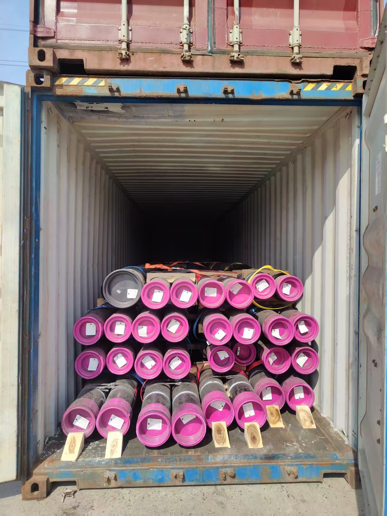
The ZC-31 full-flush 9⅝″ P110 shipment for an African operator — the outer string described in the note above, not a 7″ string. Protectors go on before loading, so the diameter the annulus sum is run against is fixed long before anyone at the rig can measure it.
At a Glance: the Five Weights You Can Actually Order in P110 at 7″
Masses, wall thickness and the end-finish letters are API 5CT 11th Edition Table C.1, column 12. Inside diameter, drift and plain-end mass come from Table C.18 and Table E.18, which carry those columns; Table C.1 does not. Drift is Table C.23's casing deduction, d − 3.18 mm.
| Mass T&C (lb/ft / kg/m) | Wall (mm / in.) | ID (mm / in.) | Standard drift (mm / in.) | Plain-end mass (kg/m / lb/ft) | End finish in P110 |
|---|---|---|---|---|---|
| 26.00 / 39.14 | 9.19 / 0.362 | 159.42 / 6.276 | 156.24 / 6.151 | 38.21 / 25.69 | PLB |
| 29.00 / 43.60 | 10.36 / 0.408 | 157.08 / 6.184 | 153.90 / 6.059 | 42.78 / 28.75 | PLB |
| 32.00 / 47.92 | 11.51 / 0.453 | 154.78 / 6.094 | 151.60 / 5.969 | 47.20 / 31.70 | PLB |
| 35.00 / 52.09 | 12.65 / 0.498 | 152.50 / 6.004 | 149.32 / 5.879 | 51.52 / 34.61 | PLB |
| 38.00 / 56.10 | 13.72 / 0.540 | 150.36 / 5.920 | 147.18 / 5.795 | 55.52 / 37.29 | PLB |
Read the end-finish column first, because it is the column the industry skips. PLB is plain-end, long round and buttress — and the absent S means short round is not offered in this grade at this size, at any of the five masses. Short round does exist at 7″ — Table C.1 shows PS in the H40 column and PSLB in the J55/K55 column at the light masses — so it is the grade, not the size, that removes it. Note too that plain-end mass is not the ordered mass: 38.21 kg/m against a 26.00 lb/ft (39.14 kg/m) designation, because the designation includes threads and coupling.
One drift value in that column is worth checking against whatever datasheet you are holding. Datasheets in circulation publish the 7″ 29.00 lb/ft drift as 6.125 in. Table E.18 gives 6.059 in. — the tabulated 6.184 in. ID less 1/8 in. — and Table E.24 lists no alternative drift at 29.00 lb/ft. The published figure is 0.066 in. oversize, which is the dangerous direction, and it cannot be a connection artefact: a connection can pull the drift below ID − 1/8 in., never raise it above. That 6.125 is exactly 6⅛, which looks like the deduction having been copied across as the drift instead of subtracted from the ID — an inference about how it happened, not something any datasheet states.
7″ P110 is not unavailable; it is unavailable at eight of the thirteen 7″ masses. Column 12 is dashed at 17.00, 20.00 and 23.00 lb/ft at the light end and at 42.70, 46.40, 50.10, 53.60 and 57.10 lb/ft at the heavy end. The heavy tail is not absent from the standard — it is listed in the C90/T95 and C110 columns — but there it reads P, plain-end only, with no threaded end finish at all. Q125 at 7″ is narrower still: 35.00 and 38.00 lb/ft, nothing else. Asserting the grade across all thirteen rows is a recurring published error at this size, and where we have traced it the mechanism is the same — a page prints the grade-independent dimension table and asserts one grade against every row of it. Availability is Table C.1; dimensions are Table C.18; they are different tables and they disagree.
One route exists to a wall between the five — not to a mass outside them. Table C.1 footnote e: "For casing with S, L, B connections, intermediate wall thicknesses are allowed in accordance with 4.2.3 and 7.2 and API 5B." Clause 7.2 confines that to walls "within the particular S, L, or B series of wall thicknesses and grade for the applicable Label 1 size specified in Table C.1" — the interior of the series available in the grade, which is why it cannot reach 42.70 lb/ft in P110 and cannot go below 26.00. It is an agreement item under 4.2.3, not a catalogue item. What it does answer is "we need 0.47 in. and the table jumps from 0.453 to 0.498", where both bracketing rows are P110-available.
The Coupling OD Decision: Long Round, Buttress Regular, or Buttress Special Clearance
Long round and buttress start from the same coupling diameter
| API 5CT Table C.27 / C.28 at 7″ | Long round (LTC) | Buttress regular (BTC) | Buttress special clearance |
|---|---|---|---|
| Coupling outside diameter | 200.03 mm (7.875 in.) | 200.03 mm (7.875 in.) | 187.32 mm (7.375 in.) |
| Minimum length NL | 228.60 mm (9.000 in.) | 254.00 mm (10.000 in.) | 254.00 mm (10.000 in.) |
| Recess / counterbore Q | 180.18 mm | 181.36 mm | 181.36 mm |
| Width of bearing face b | 7.94 mm | 7.94 mm | not specified — 8.6 excepts b |
| Coupling mass | 13.92 kg | 13.98 kg | 6.28 kg |
| Tolerance on outside diameter | ±1 %, capped at ±3.18 mm (±2.00 mm here) | ±1 %, capped at ±3.18 mm (±2.00 mm here) | +0.79 / −0.40 mm |
The first row is the one that surprises people. A long round coupling and a regular buttress coupling are the same 200.03 mm outside diameter at 7″, so the instinct that long round is the slimmer connection buys nothing in the annulus — only a shorter coupling, 228.60 mm against 254.00 mm. The bearing-face row is a clause, not a table entry: Tables C.27 and C.28 tabulate b without qualification, and it is 8.6's final paragraph that says special clearance couplings conform to the tabulated dimensions "(except b)". The tolerance row matters as much: special clearance carries a tight +0.79 / −0.40 mm band rather than the ±1 % governing regular couplings, because that diameter is one somebody downhole is relying on. At 200.03 mm, ±1 % is ±2.00 mm, and that band belongs in the clearance sum. Read footnote b of C.27/C.28 whole, though — it is "±1 % but not greater than ±3.18 mm", and the cap does not bind at 7″ but does from 13⅜″ upward, where the percentage alone would overstate the tolerance.
Only buttress can be reduced — and that is a clause, not a market habit
API 5CT 8.6, "Special Clearance Couplings—All Grades Except Q125", reads: "When specified in the purchase agreement, special clearance (reduced outside diameter Wc) couplings for buttress casing and EU tubing shall be furnished." Only 8.6 states the restriction. Table C.1 footnote d is affirmative rather than exclusive — "Buttress casing is available with regular, special clearance couplings or special clearance couplings with special bevel" — so it corroborates the scope without imposing it, and Table C.27, the round thread casing coupling table, corroborates it again by carrying no special clearance column at any size. One clause, two corroborations.
The procurement consequence is the point of this page: an order that fixes long round has not merely chosen a thread form, it has removed the reduced-OD coupling from what can be done later, while gaining no clearance in exchange. Buttress keeps the option open at the same diameter and no cost. Wider trade-off: casing connection types: STC, LTC, BTC and premium → and the API 5CT specification tables →.
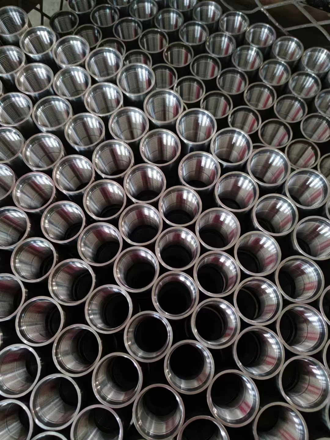
Machined API couplings stood on end. The wall visible between the thread and the outside surface is the dimension Table C.7 calls critical thickness — and it is the dimension a special clearance coupling spends.
What special clearance costs, in one number
Table C.7, Critical Thickness for Couplings with API Threads, gives the 7″ regular buttress coupling 13.46 mm (0.530 in.) and the special clearance version 7.11 mm (0.280 in.) — a 47 % reduction. The arithmetic shows where it went. The diameter falls 200.03 − 187.32 = 12.71 mm (0.500 in.), which is 6.36 mm per side; the critical thickness falls 13.46 − 7.11 = 6.35 mm. Within a hundredth of a millimetre, every bit of diameter removed comes off the coupling wall. Minimum length stays at 254.00 mm and the counterbore at 181.36 mm, so thread engagement is untouched — the mechanism is wall, not threads. For contrast, the round thread column gives a 7″ long round coupling 14.43 mm (0.568 in.), thicker than buttress, with no reduced version to compare against.
There is exactly one rack-level tell, and it is paint. Half an inch of diameter is not something anyone eyeballs reliably on a loaded truck. API 5CT 10.4.4 closes the gap: for all grades except L80 3Cr, 9Cr and 13Cr, the entire circumferential surface of a special clearance coupling is painted, "including the appropriate colors and a black band around the center." On P110 that is a white coupling with a black centre band, against a plain white coupling for regular. The receiving check is therefore to caliper the OD against 200.03 or 187.32 mm and confirm the paint agrees — caliper first, band as the cross-check, because paint is the first thing transit damages.
The Annulus Check Is Against the Outer String's Drift, Not Its ID
Radial clearance is computed against the drift of the outer string, because the drift is what that string is guaranteed to pass along its whole length; the inside diameter is a nominal figure no tool is entitled to rely on. From 9⅝″ to 13⅜″ the two differ by 3.97 mm (Table C.23) — 1.99 mm per side, small in absolute terms and large against the gaps that decide this. Clearance below is (drift − coupling OD) ÷ 2.
| Outer string (9⅝″) | Drift (mm / in.) | Radial gap, BTC regular 200.03 mm | Radial gap, special clearance 187.32 mm |
|---|---|---|---|
| 43.50 lb/ft | 218.41 / 8.599 | 9.19 mm (0.362 in.) | 15.55 mm (0.612 in.) |
| 47.00 lb/ft | 216.54 / 8.525 | 8.26 mm (0.325 in.) | 14.61 mm (0.575 in.) |
| 53.50 lb/ft | 212.83 / 8.379 | 6.40 mm (0.252 in.) | 12.76 mm (0.502 in.) |
| 58.40 lb/ft | 210.29 / 8.279 | 5.13 mm (0.202 in.) | 11.49 mm (0.452 in.) |
| 70.30 lb/ft | 203.23 / 8.001 | 1.60 mm (0.063 in.) | 7.96 mm (0.313 in.) |
| 75.60 lb/ft | 200.02 / 7.875 | none — both 7.875 in. (200.02 / 200.03 mm are two roundings of the same value) | 6.35 mm (0.250 in.) |
The top four rows are the normal case, decided on cost and running practice rather than geometry. The bottom two are where the page earns its keep. At 9⅝″ 75.60 lb/ft the drift and the coupling are both 7.875 in. in the USC tables — so a regular 7″ buttress coupling has no nominal clearance at all, and special clearance is not an optimisation but the only API route. At 70.30 lb/ft the nominal 1.60 mm per side sits inside the coupling tolerance: apply the +1 % and the coupling becomes 202.03 mm, leaving 0.60 mm before anything else is considered. Two cautions go with the table. Those two 9⅝″ rows are listed in Table C.1 as P, plain-end only, so such a string carries a premium connection whose outside diameter is in no API table and must be read off the licensor's datasheet. And the real restriction is often neither the casing nor the coupling: a liner hanger body, a packer bore or a tieback receptacle can be the tightest point in the string, and none of them appears in API 5CT. Size the string with the pipe grade selector →, but take the restriction from the completion drawing.
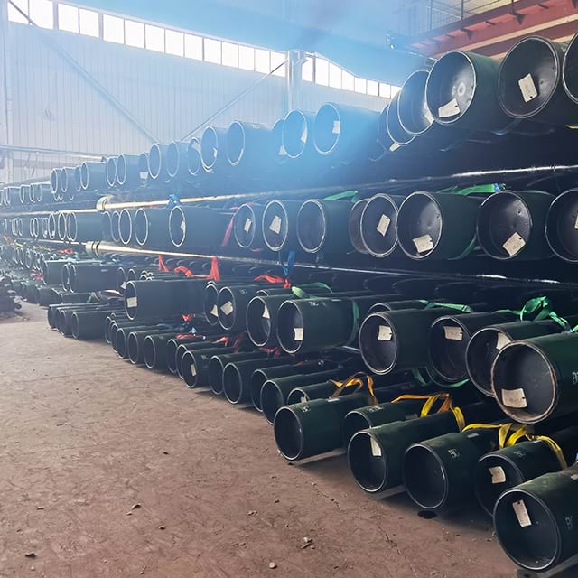
Casing racked with couplings made up and every joint tagged. The coupling diameter is fixed at this point; the annulus it has to pass is fixed on the outer string's purchase order, months earlier.
Drift at 7″: One Alternative in the Table, Four in the Purchase Agreement
API 5CT 7.10: "Each length of pipe shall be drift-tested throughout its entire length." Table C.23 puts 7″ in the casing band below Label 1: 9⅝, which sets a 152 mm (6 in.) mandrel at d − 3.18 mm (1/8 in.) — the source of the drift column above. Where the pipe was drifted full-length before the couplings went on, 7.10 also requires re-drifting a minimum of 0.6 m (24 in.) from the coupled end on casing after power-tight make-up; name that step in a third-party inspection scope, because a mill-floor procedure most often treats it as already satisfied.
Alternative drift is where 7″ gets awkward. Table C.24 tabulates an alternative mandrel at only two 7″ masses — 23.00 lb/ft at 158.75 mm (6.250 in.) and 32.00 lb/ft at 152.40 mm (6.000 in.) — and 23.00 lb/ft is one of the rows dashed in the P110 column. So exactly one of the five orderable masses has a tabulated alternative, and on 26.00, 29.00, 35.00 and 38.00 lb/ft the mandrel must be written into the purchase agreement under 7.10 b): "pipe in sizes and masses not in Table C.24 or Table E.24 shall be tested with the alternative drift mandrels as specified in the purchase agreement." A line reading "alternative drift per Table C.24" specifies nothing on four of the five. The 32.00 lb/ft entry also runs opposite to the assumption behind it: its standard drift is 151.60 mm (5.969 in.) and the tabulated alternative is 152.40 mm (6.000 in.) — 0.80 mm larger, a stricter test, not a looser one. Table C.43 sequence 14 fixes the mark: D for standard drift, DA plus the mandrel size for an alternative one.
7″ sits inside the tubing-service crossover, and one purchaser election moves three things at once. Table C.23 footnote b carries the marking obligation and nothing else: "Casing sizes larger than Label 1: 4½ but smaller than Label 1: 10¾ specified by the purchaser to be used in tubing service shall be marked as specified in Section 10." The consequences follow from the mark rather than from the footnote. The mark is DT42, Table C.43 sequence 14, and 9.13.5 routes it to the tubing rule — "See 7.10 for requirements for casing used as tubing." So the diameter deduction does not change, because the tubing band above 2⅞ to 8⅝ is also d − 3.18 mm, but the mandrel length goes from 152 mm to 1067 mm (6 in. to 42 in.), and a rigid gauge seven times longer finds straightness deviation and local ovality the short one passes without noticing. The lengths come from Table C.22's own "Tubing and casing used as tubing" row: R1 6.10 to 7.32 m, R2 8.53 to 9.75 m and R3 11.58 to 12.80 m, each at a 0.61 m permissible variation — against casing's own R2 of 7.62 to 10.36 m (25 to 34 ft) at 1.52 m and R3 of 10.36 to 14.63 m (34 to 48 ft). Tubing service therefore belongs on the purchase order, not in an email.
Where the Pressure Ratings Come From
API Bulletin 5C3 works its own combined-load collapse example on exactly this pipe — 7″ OD, 26.00 lb/ft, Grade P110 — so this is the one casing combination where the standard publishes a worked case rather than only a formula. The derivation, with the axial-derating step and the regime selection that decides the answer, is on the P110 grade page →; the equations are in the API 5C3 calculation reference → and a specific case runs through the collapse calculator →. Joint strength is a separate calculation with its own equations in API 5C3 Section 5, and it needs the connection geometry rather than the pipe body alone: joint strength calculator →. One adjacent figure, stated so it cannot be inverted: under 9.12.3 the standard hydrostatic test pressure computes to 62.5 MPa on the 26.00 lb/ft row and above the 69.0 MPa (10,000 psi) ceiling on all four heavier rows, which therefore certify at 69.0 MPa. That is the clause's ceiling, not the pipe's limit.
Check the basis before you check the number. Two documents can publish different collapse, burst and body-yield ratings for the same 7″ joint without either being wrong — one computed on nominal wall for new pipe, another on a remaining wall for an inspection class, a third on a different edition's coefficients. The habit that separates them is recording, on the design sheet, which basis and which edition produced each figure before the figure is used. A rating without a basis is not a rating; it is a quantity someone else derived under assumptions you have not seen.
The Grade Is Already Decided
P110 is on a 7″ string because the burst or collapse case needs more than the 80 ksi grades, and its envelope is fixed and narrow to describe: minimum yield 758 MPa (110 ksi), maximum yield 965 MPa (140 ksi), minimum tensile 862 MPa (125 ksi), elongation under load 0.6 % (Table C.5), quenched and tempered (Table C.3, column 4). Everything else about the grade — the chemistry that Table C.4 barely restricts, the NDE acceptance levels, the straightening clause, the certificate content — is on the P110 grade page →. Three points belong here rather than there, because they attach to orders. A "≤ 32 HRC" hardness limit for P110 circulates widely and is now embedded in AI-generated answers; it is not in API 5CT. The P110 row of Table C.5 is dashed in the HRC column, the HBW column and the allowable hardness variation column alike — there is no maximum hardness for P110 in this standard, not 32 HRC and not any other figure. Whether a given well permits P110 at all is decided by NACE MR0175 / ISO 15156, a separate document this page does not restate: run the conditions through the sour service selector →. And the phrase "product specification level" does not occur anywhere in API 5CT 11th Edition — every PSL string on a 5CT order is an end-finish code (P, S, L, B) being misread, not a quality level.
When NOT to Run 7″ P110
- When the load case needs a wall outside the five-row band. Above 13.72 mm (0.540 in.) at 7″, P110 stops. Q125 continues only at 35.00 and 38.00 lb/ft, so it adds yield, not wall. The 42.70 to 57.10 lb/ft rows exist in C90/T95 and C110 — and there as plain-end only, which makes a premium connection part of that decision rather than a later option.
- When the outer string will not take even a special clearance coupling. Below the 9⅝″ 75.60 lb/ft drift, or inside a liner hanger or packer bore tighter than 187.32 mm, the API coupling ladder has run out. The answer is a flush or semi-flush premium connection, or a smaller string — not a regular coupling with a note in the running procedure.
- When the string must hold gas across the connection. Long round and buttress both seal on thread compound in the thread helix; neither carries a metal-to-metal seal surface. That decision is premium regardless of mass, grade or coupling class: BTC versus premium connections →.
- When the well is sour. API 5CT builds no sour-service control into P110 at any size — no hardness ceiling and no SSC test clause. That routes to a different grade, not to a supplementary requirement.
Purchase Order: The Complete 7″ P110 Spec
Seven lines, all specific to this combination. Inspection scope, certificate content and total-cost modelling are in the P110 procurement and running-cost guide →.
- Mass, from the five: "7″, 29.00 lb/ft" — not a range, and not a mass outside 26.00 to 38.00, which Table C.1 column 12 does not list in this grade.
- Connection: "LTC" or "BTC" as the end finish. Both are offered at all five masses; BTC preserves the special clearance option and LTC removes it, at the same 200.03 mm coupling diameter.
- Process, if electric-welded: 5.1 reads that "electric-welded Grade P110 pipe and Grade Q125 casing shall be provided only when the SR in A.6 (SR 11) is specified in the purchase agreement" — a shall…only clause, so an EW P110 order without SR 11 named is not a compliant order. Table 3 routes SR 11 under NDE. Table C.3 footnote g also tightens electric-welded P110 chemistry to 0.020 % P and 0.010 % S, against the 0.030 / 0.030 of Table C.4 footnote e. Silence on process is not an error; it means seamless.
- Coupling class: "regular" or "special clearance", as its own line. Silence selects regular, and the mill ships 200.03 mm couplings entirely compliantly against an order that needed 187.32 mm.
- Alternative drift, where required: at 26.00, 29.00, 35.00 and 38.00 lb/ft state the mandrel diameter and length explicitly, citing 7.10 b), because Table C.24 has no row to point at. At 32.00 lb/ft "alternative drift per Table C.24" is a complete instruction and means 152.40 mm × 152 mm.
- Tubing service, if applicable: "specified for tubing service per Table C.23 footnote b" — this selects the 1067 mm mandrel, the tubing range lengths in Table C.22 and the DT42 mark under Section 10.
- Intermediate wall, if needed: cite Table C.1 footnote e with 4.2.3, 7.2 and API 5B, state the wall in inches and millimetres, and agree it with the mill before the order is placed — 7.2 keeps it inside the P110 series, between 0.362 and 0.540 in.
Two checks close the loop on receipt. Caliper the coupling outside diameter against the class ordered — 200.03 mm at ±2.00 mm, or 187.32 mm at +0.79 / −0.40 mm — and confirm the paint agrees. Then read the drift mark: D, DA with a size, or DT42, and confirm it matches the order rather than the mill's default.
Frequently Asked Questions
What weights of 7 inch P110 casing can I actually order?
Five: 26.00, 29.00, 32.00, 35.00 and 38.00 lb/ft, which is 39.14 to 56.10 kg/m nominal threaded-and-coupled mass. API 5CT 11th Edition Table C.18 lists thirteen 7 inch casing rows, but dimensions are grade-independent and availability is not — availability lives in column 12 of Table C.1, and that column is dashed at 17.00, 20.00 and 23.00 lb/ft and again across the whole heavy tail from 42.70 to 57.10 lb/ft. A supplier offering 7 inch P110 from 17 to 57 lb/ft is quoting the dimension table and asserting the grade against all of it.
Is 7 inch P110 casing available with short round (STC) thread?
No. Every one of the five 7 inch P110 rows in API 5CT Table C.1 reads PLB, where P is plain-end, L is long round thread and B is buttress thread. Short round appears at 7 inch in the H40, J55 and K55 columns at the light masses, so the thread form exists at this size — it is simply not offered in Grade P110 at any 7 inch mass. Specifying 7 inch P110 STC asks for a product the standard does not list.
What is the coupling OD on 7 inch P110 casing?
200.03 mm (7.875 in.) for both a long round coupling per API 5CT Table C.27 and a regular buttress coupling per Table C.28 — the two are the same diameter at this size, so choosing long round buys no clearance. A special clearance buttress coupling is 187.32 mm (7.375 in.), which is 12.71 mm (0.500 in.) smaller. Tolerance on the regular coupling is plus or minus 1 percent, so plus or minus 2.00 mm at this diameter, against plus 0.79 mm and minus 0.40 mm on the special clearance diameter.
Will 7 inch casing couplings pass through 9 5/8 inch casing?
Through most 9 5/8 inch strings, yes, and the sum is run against the outer string's drift rather than its inside diameter. A 200.03 mm regular coupling leaves 9.19 mm of radial clearance inside 9 5/8 inch 43.50 lb/ft, 8.26 mm inside 47.00 lb/ft and 6.40 mm inside 53.50 lb/ft. It stops at the bottom of the 9 5/8 inch ladder: the 75.60 lb/ft drift is 200.02 mm, which is 7.875 in. — exactly the coupling diameter — so a regular 7 inch coupling has zero nominal clearance there and a special clearance coupling is the only API answer.
When do I need special clearance couplings on 7 inch casing, and what do they cost?
You need them when the outer string drift will not accept 200.03 mm with a workable margin, and the cost is paid in coupling wall rather than in thread engagement. API 5CT Table C.7 gives the critical thickness for a 7 inch regular buttress coupling as 13.46 mm (0.530 in.) and for the special clearance version as 7.11 mm (0.280 in.) — a 47 percent reduction. Minimum coupling length stays at 254.00 mm and the counterbore stays at 181.36 mm, so the threads are unchanged; the metal comes off the outside. Clause 8.6 restricts the option to buttress casing and EU tubing, so a long round order forecloses it.
What is the collapse pressure of 7 inch 26 lb/ft P110 casing?
It is not a single number, because it depends on the axial load and on which of the four API 5C3 collapse regimes the D/t ratio falls in. API Bulletin 5C3 happens to work its own combined-load example on exactly this joint — 7 inch OD, 26 lb/ft, Grade P110 — and shows the geometry sitting in the plastic regime rather than the yield-strength regime that a thick-walled joint is often assumed to occupy. The full derivation, with the axial derating step, is worked line by line on the API 5CT P110 grade page, and any specific case should be run through the collapse calculator with the actual axial stress.
Does 7 inch P110 casing need a drift test, and can I specify a different drift?
API 5CT 7.10 requires that each length of pipe be drift-tested throughout its entire length, and Table C.23 fixes the mandrel for casing below Label 1: 9 5/8 at 152 mm long and d minus 3.18 mm in diameter. Casing is then re-drifted a minimum of 0.6 m (24 in.) from the coupled end after power-tight make-up where it was drifted full-length before the couplings went on. An alternative drift is a purchaser election, but Table C.24 tabulates only two 7 inch masses — 23.00 and 32.00 lb/ft — and 23.00 is not orderable in P110, so on four of the five P110 masses the mandrel has to be written into the purchase agreement under 7.10 b) and the pipe is then stencilled DA with the mandrel size under Table C.43.